

Magnetic levitation centrifugal pump
- Summary
- Abstract
- Description
- Claims
- Application Information
AI Technical Summary
Benefits of technology
Problems solved by technology
Method used
Image

Examples
Embodiment Construction
[0011]The main aim of the present invention is to devise a magnetic levitation centrifugal pump which allows reducing the damage of the blood due to its interaction with the rotor element.
[0012]Within this aim, one object of the present invention is to reduce the formation of air bubbles inside the pump itself.
[0013]Another object of the present invention is to avoid blood stagnation inside the relevant hollow body.
[0014]Yet another object is to optimize the ratio between the head of the pump and the turbulence inside it.
[0015]Another object of the present invention is to devise a magnetic levitation centrifugal pump which allows overcoming the aforementioned drawbacks of the prior art in the ambit of a simple, rational, easy, effective to use and low cost solution.
[0016]The aforementioned objects are achieved by the present magnetic levitation centrifugal pump having the characteristics of claim 1.
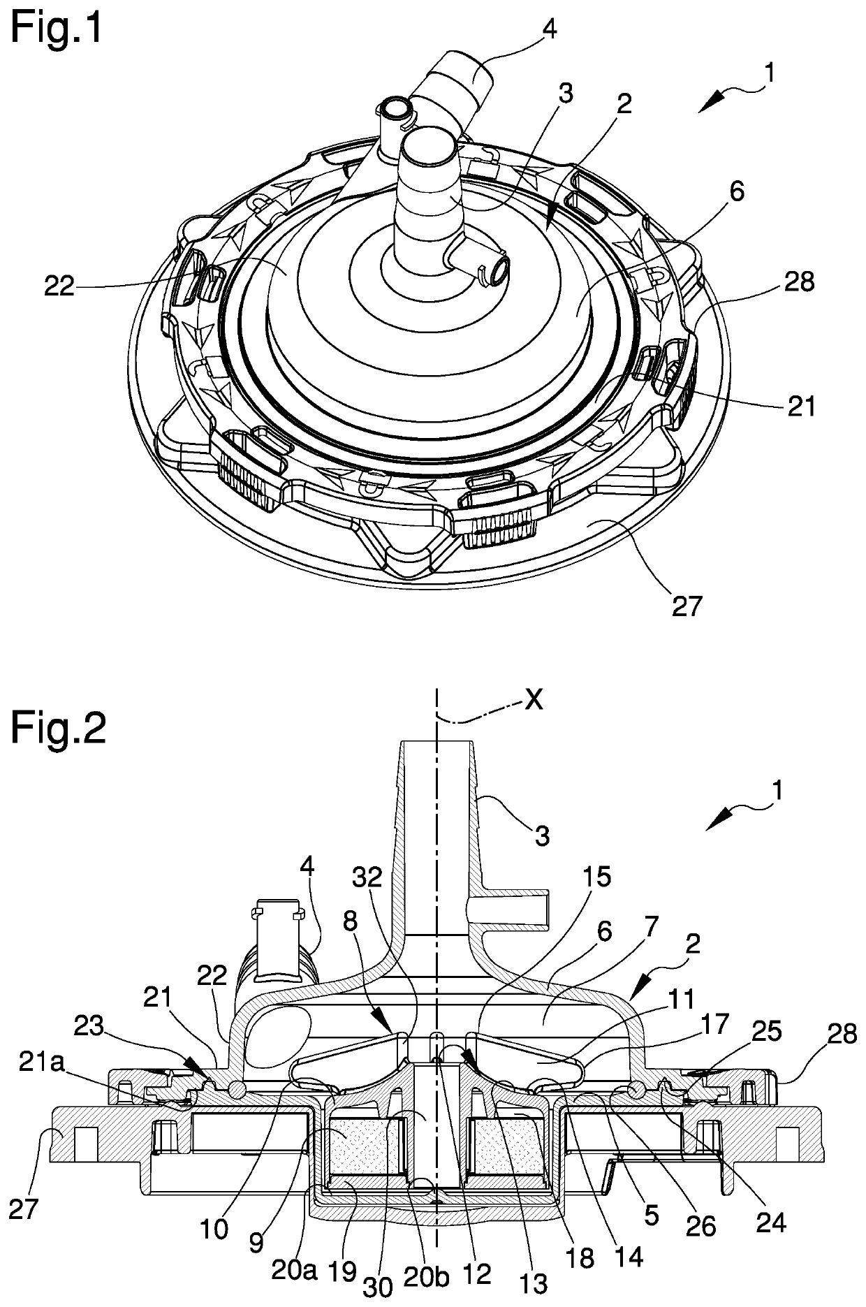
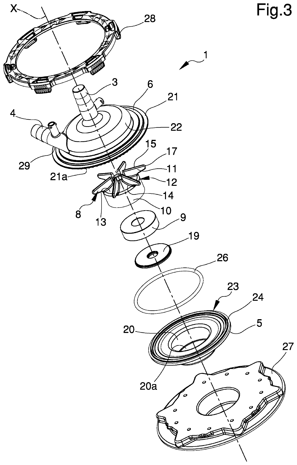
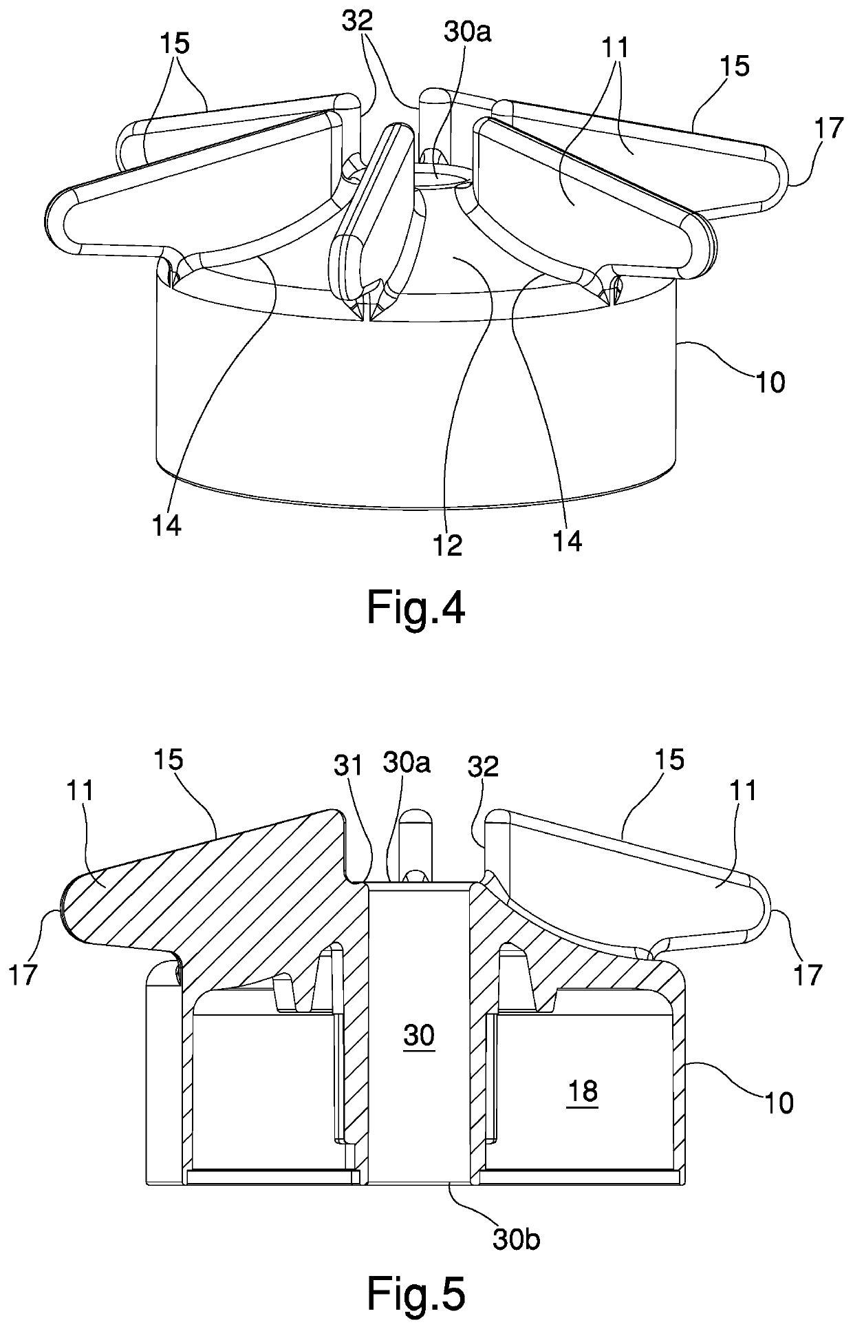
BRIEF DESCRIPTION OF THE DRAWINGS
[0017]Other characteristics and advantages of the pr...
PUM
 Abstract
Description
Claims
Application Information