This helps you quickly interpret patents by identifying the three key elements:
Problems solved by technology
Method used
Benefits of technology
Benefits of technology
The patent describes a device that reduces vibrations and improves the quality of filtration during operation. It uses damping means that provide a progressive damping effect. The device also includes an assistance means that helps to return the piston to its engaged position, and increases the axial stress exerted on the piston, resulting in more important torque transmission. The clutch engagement time is also reduced, and the device is normally closed. The device achieves balanced pressures on either side of the piston, and reduces the risk of deformation of the piston. A friction lining may also be used to further reduce the risk of piston deformation.
Problems solved by technology
Besides, such clutch means have a little complex structure, and require few parts.
Method used
Image
Click on the blue label to locate the original text in one second.
Reading with bidirectional positioning of images and text.
Examples
first embodiment
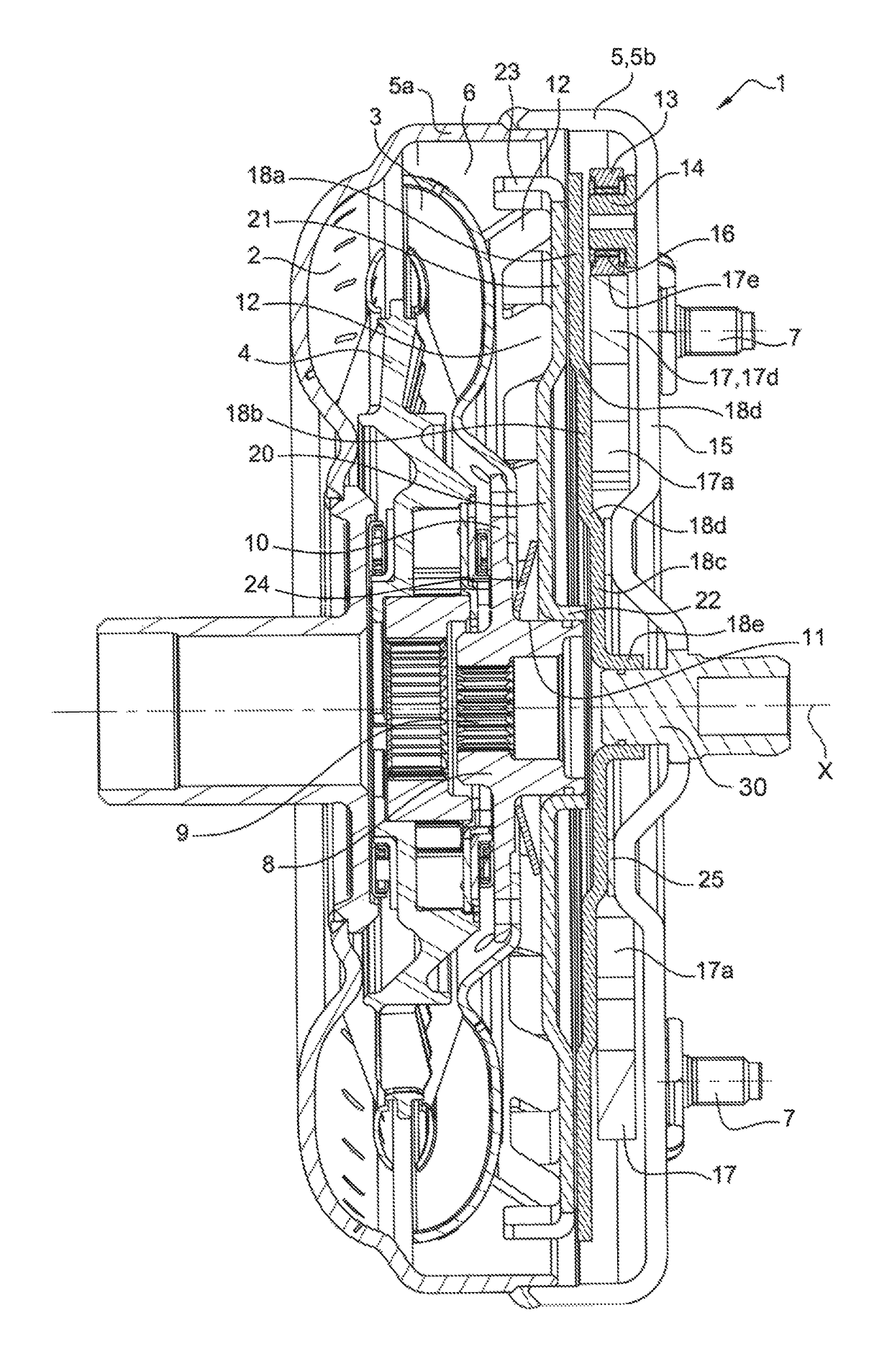
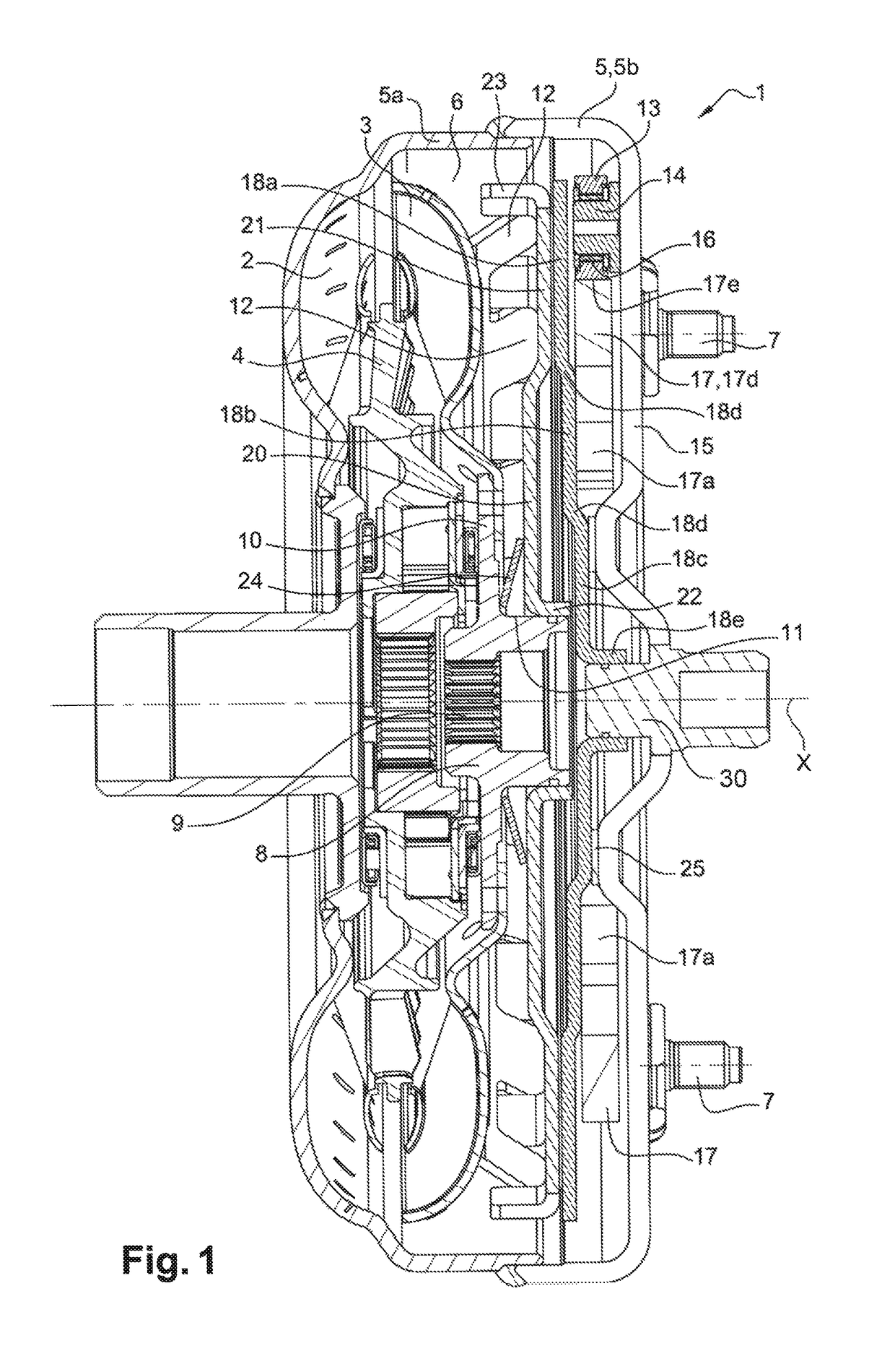
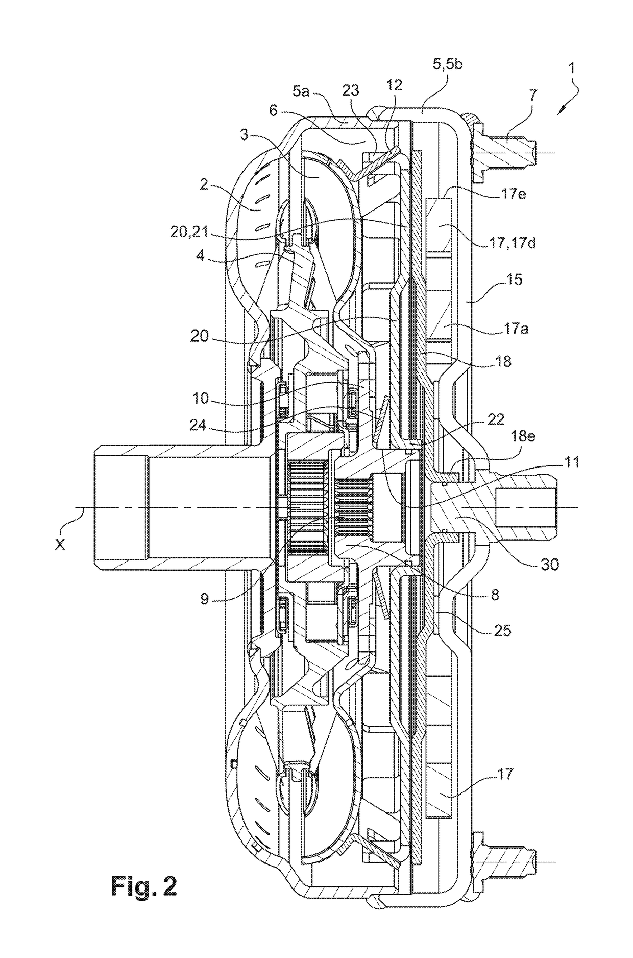
[0059]FIGS. 1 to 2 illustrate a torque converter according to the invention. Such device makes it possible to transmit a torque from the output shaft of an internal combustion engine in a motor vehicle, such as for instance a crankshaft, to a transmission input shaft. The axis of the torque converter 1 bears reference X.
[0060]In the following, the words “axial” and “radial” are defined relative to the X axis.
[0061]The torque converter 1 comprises an impeller bladed wheel 2, able to hydrokinetically drive a turbine bladed wheel 3 through a reactor 4.
[0062]The impeller wheel 2 is fastened to a cover 5 consisting of two bell-shaped parts 5a, 5b assembled together by welding and defining an internal volume 6 accommodating the impeller wheel 2, the turbine wheel 3 and the reactor 4. Said cover also more generally referred to as the cover 5, comprises fastening means 7 making it possible to rotationally couple said cover 5 with the crankshaft.
[0063]The torque converter 1 further comprises...
third embodiment
[0093]FIGS. 4 and 5 show a part of a torque converter 1 according to the invention, which is different from the ones disclosed above while referring to FIGS. 1 to 3 in that the torque input element comprises a supporting cage comprising two spaced apart partitions 26, 27 connected together by axially extending spacers 28.
[0094]The spacers 28 may be provided as a single piece with one of the partitions 26, 27, as in the case shown in FIGS. 4 and 5.
[0095]The shaft 14 comprises a first and a second axial end 14a engaged into openings having a matching shape in the partitions 26, 27, with the shaft 14 further comprising an axially median portion 14b used for supporting the leaf 17 and axially located between the two partitions 26, 27. The shaft 14 is thus not cantilevered, and the stresses can be taken up at each end 14a of the shaft 14.
[0096]The partitions 26, 27 are fixed together and to the cover 5 by rivets 29.
[0097]The cage 26, 27, 28 may of course consist, at least partially, of t...
PUM
Abstract
A torque transmitting device comprising a torque input element intended to be coupled to a crankshaft of an engine, a torque output element intended to be coupled to a transmission input shaft, damping means mounted between the torque input element and the torque output element, with the torque output element being able to pivot relative to the torque input element about an axis, against a resisting torque exerted by the damping means, with the damping means comprising at least one elastic leaf able to be elastically and radially held to rest on a support member, with the elastic leaf being adapted to bend upon rotation of the torque input element relative to the torque output element, with the device further comprising clutch means mounted between the torque input element and the torque output element, wherein the supporting member is carried by the torque input element.
Description
FIELD OF THE INVENTION[0001]The present invention relates to a torque transmitting device, specifically for a motor vehicle, such as a torque converter, for instance.BACKGROUND OF THE INVENTION[0002]The patent FR 2 668 234, in the name of the Applicant, discloses a torque converter comprising an impeller wheel integral with a cover intended to be coupled to an engine crankshaft, with the impeller wheel being able to hydrokinetically drive the turbine wheel through the reactor.[0003]The torque converter also comprises clutch means comprising a piston axially movable between an engaged position in which it is friction-coupled to the cover and a disengaged position in which it is uncoupled from the cover. The piston is connected to the hub through damping means. Said damping means comprise elastic springs acting circumferentially. The hub is intended to be coupled to a transmission input shaft. Besides, the turbine wheel is rotationally coupled to the hub.[0004]Pressure chambers are pr...
Claims
Application Information
Patent Timeline
Application Date:The date an application was filed.
Publication Date:The date a patent or application was officially published.
First Publication Date:The earliest publication date of a patent with the same application number.
Issue Date:Publication date of the patent grant document.
PCT Entry Date:The Entry date of PCT National Phase.
Estimated Expiry Date:The statutory expiry date of a patent right according to the Patent Law, and it is the longest term of protection that the patent right can achieve without the termination of the patent right due to other reasons(Term extension factor has been taken into account ).
Invalid Date:Actual expiry date is based on effective date or publication date of legal transaction data of invalid patent.

