
Stiffening device for a base frame of rotating machines

a technology of rotating machines and damping devices, which is applied in the direction of machine frames, machine supports, springs/dampers design characteristics, etc., can solve the problems of high vibration on rotating machinery, cumbersome process of investigating possibility of structural resonance or crack detection, and insufficient stability of structural members, so as to achieve the effect of increasing the stiffness of structural members of the base fram

Active Publication Date: 2021-01-14
BHATTACHARYA MANTOSH ISANCHANDRA
View PDF0 Cites 1 Cited by
  • Summary
  • Abstract
  • Description
  • Claims
  • Application Information

AI Technical Summary

Benefits of technology

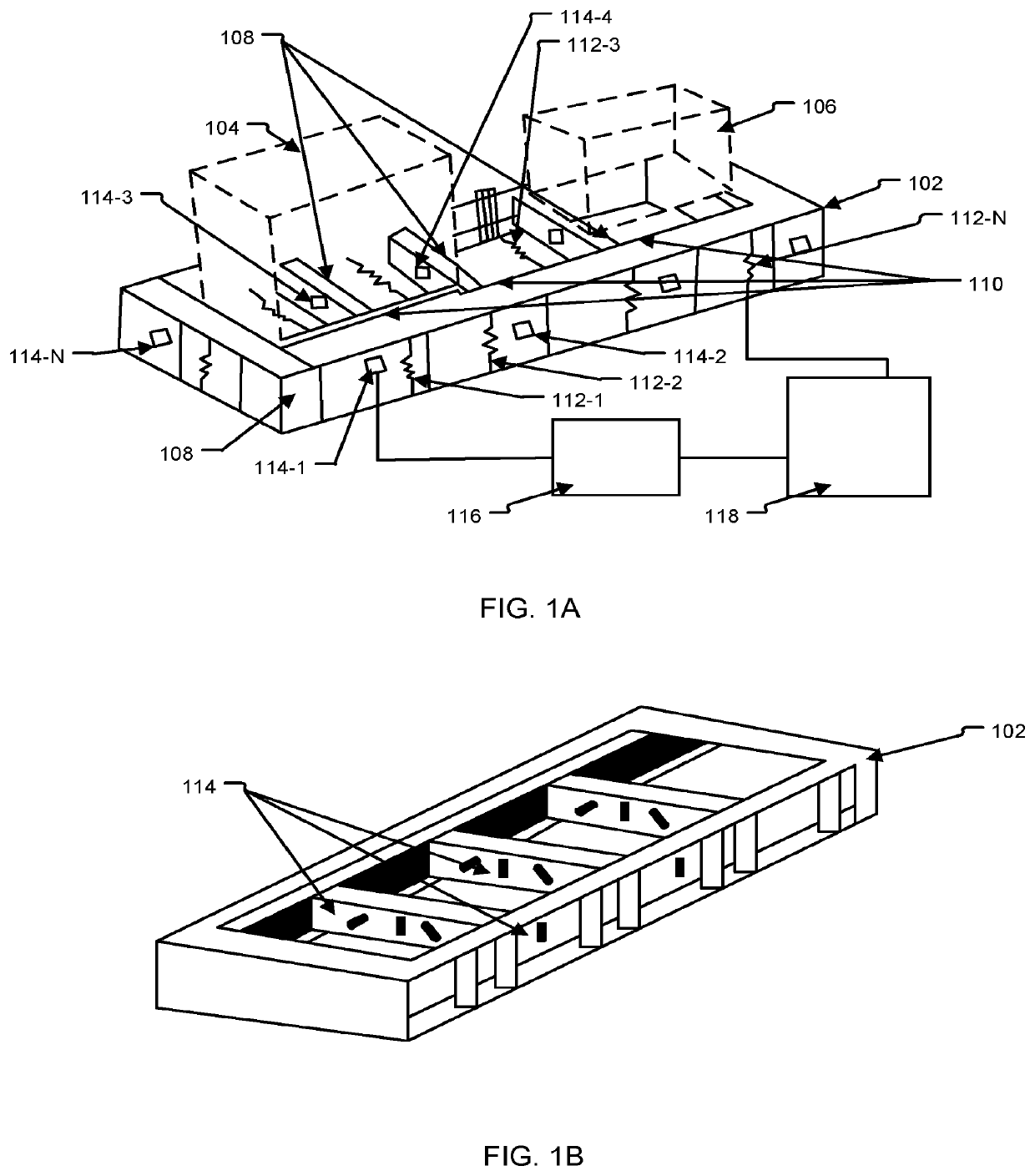
The present invention provides a stiffening device for a grout-less base frame of rotating machines to increase stiffness of its structural members. This device is simple, efficient, and cost-effective. Additionally, it can mitigate structural anomaly in a base frame of rotating machines by increasing directional stiffness of its structural members in both horizontal and vertical directions, which helps to reduce lateral and coupled modes of movement (rocking and pitching) of machinery mounted on the base frame. The device includes at least one actuated jack that is fitted at a predefined orientation with respect to the structural members for efficient stiffening of the structural members of the base frame.

Problems solved by technology

Non-grouted based frame with weak structural members in terms of directional stiffness or with any localized crack generally have more deflection than anticipated and in turn, causes high vibration on the rotating machinery.
The conventional techniques used for investigation of possibility of structural resonance or detecting a crack in structural member are cumbersome process.
These techniques includes bump test, finite element analysis (FEA), experimental modal analysis to validate the FEA and mode shapes plotting or operational deflection shape (ODS) analysis / slow motion amplified video analysis take a considerable amount of time, particularly if the machines are in remote installation.
When a crack is developed in a particular structural member of the base frame, directional stiffness gets lowered and vibration increases of machine underneath of that particular element.
Adding mass to subject under resonance is more difficult work.

Method used


Image

  • Stiffening device for a base frame of rotating machines
  • Stiffening device for a base frame of rotating machines
  • Stiffening device for a base frame of rotating machines

Examples


Embodiment Construction

[0036]The following is a detailed description of embodiments of the disclosure depicted in the accompanying drawings. The embodiments are in such details as to clearly communicate the disclosure. However, the amount of detail offered is not intended to limit the anticipated variations of embodiments; on the contrary, the intention is to cover all modifications, equivalents, and alternatives falling within the spirit and scope of the present disclosure as defined by the appended claims.

[0037]If the specification states a component or feature “may”, “can”, “could”, or “might” be included or have a characteristic, that particular component or feature is not required to be included or have the characteristic.

[0038]Exemplary embodiments will now be described more fully hereinafter with reference to the accompanying drawings, in which exemplary embodiments are shown. This disclosure may however, be embodied in many different forms and should not be construed as limited to the embodiments ...


PUM


Abstract

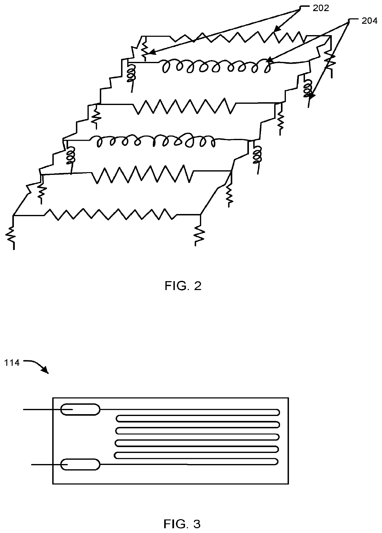
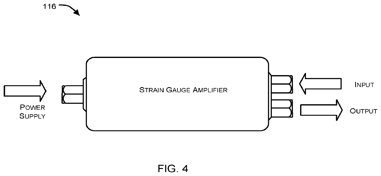
A stiffening device for a base frame is disclosed. The disclosed stiffening device comprises hydraulic jacks fitted with structural members of the base frame; stain gauges coupled to the structural members of the base frame, the stain gauges configured to detect deformation in the structural members of the base frame and generate first signals based on the detected defamation in the structural members; at least one signal conditioner unit coupled to the strain gauges to receive the first signals and generate second signals by performing any or a combination of amplification, filtering and conversion of the received first signals; and a hydraulic console configured to actuate at least one of the hydraulic jacks when value of received second signals is above a predefined threshold value. Upon actuation, the actuated at least one of the jacks stiffens at least one of the structural members of the base frame.

Description

TECHNICAL FIELD[0001]The present disclosure relates to the technical field arrangements for mitigating structural anomaly in base frames. More specifically, it pertains to a stiffening device for mitigating structural anomaly in a grout-less base frame of a rotating machine.BACKGROUND OF THE INVENTION[0002]Background description includes information that may be useful in understanding the present invention. It is not an admission that any of the information provided herein is prior art or relevant to the presently claimed invention, or that any publication specifically or implicitly referenced is prior art.[0003]Base frames are required for mounting rotating machinery / devices. Non-grouted based frame with weak structural members in terms of directional stiffness or with any localized crack generally have more deflection than anticipated and in turn, causes high vibration on the rotating machinery. When a rocking / pitching motion at particular direction of rotating machine is observed...

Claims


Application Information

Patent Timeline
Patent Type & Authority Applications(United States)
IPC IPC(8): F16M7/00F16M5/00
CPCF16M7/00F16M5/00F16F15/002F16F15/0275F16F2230/08F15B15/1404F15B2211/7107
Inventor BHATTACHARYA, MANTOSH ISANCHANDRA
Owner BHATTACHARYA MANTOSH ISANCHANDRA
Learn More