Optical fiber calibration connector

a technology connectors, applied in the field can solve the problems of significant optical insertion losses, complicated workflow, and confusion of analysis, and achieve the effects of improving reliability, facilitating the mating of optical fiber connectors, and improving the accuracy of measured spectrum

Active Publication Date: 2018-10-09
KONINKLJIJKE PHILIPS NV
View PDF11 Cites 1 Cited by
  • Summary
  • Abstract
  • Description
  • Claims
  • Application Information

AI Technical Summary

Benefits of technology

[0010]The connector may thus be used to mate a first group of one or more optical fibers, with one or more corresponding optical fibers in a second group of one or more optical fibers. Consequently an optical path may be formed between corresponding optical fibers in the first and second groups. The shutter prevents debris such as dust and sand from entering the connector, which if present in an optical connector would otherwise degrade the lifetime of the connector due to abrasion of the mating optical fiber cores. Furthermore, since the first port is accessed by applying a force to the outer surface of the shutter; the shutter can be opened with the insertion force of the first group of one or more optical fibers as it is inserted into the port. The simplified insertion mechanism facilitates insertion of the first group with a single hand, thereby improving workflow. Furthermore, when a second group of one or more optical fibers is received within the second port, the orientation of the shutter respective the second group and the inherent non-zero reflectance of the inner surface permits the use of the inner surface as an optical reference surface for use in calibrating the second group of one or more optical fibers.
[0014]In accordance with another aspect of the invention the optical fiber connector includes a debris collection zone. Advantageously, any dust or sand or particles that enter into the cavity become trapped at the debris collection zone where they are immobilized, thereby preventing abrasion of the mating surfaces of the optical fiber cores.
[0016]In accordance with another aspect of the invention another optical fiber connector arrangement is disclosed. In this arrangement the shutter of the optical fiber connector is in the open state, and the optical fiber connector arrangement includes a first group of one or more optical fibers. The first group is received within the first port such that the first group at least partially fills the cavity. Furthermore the first group is arranged respective the second group such that each optical fiber in the first group is in optical communication with one or more corresponding optical fibers in the second group. The shutter, being openable by applying a force to the outer surface of the shutter in a direction along the common axis allows the conversion of the connector between a closed state in which any one of dust or light is prevented from entering into the connector, or in which an optical calibration or dark measurement can be carried out, and a connected state in which optical communication between corresponding optical fibers in the first and second groups is achieved.
[0021]In accordance with another aspect of the invention another computer program or computer program product is disclosed. This comprises instructions which when executed on a computer cause the computer to perform the following steps: identify, based on the predetermined optical signature of the inner surface of the shutter, whether the shutter of the optical connector arrangement of claim 10 is in the closed state; measure a reference optical spectrum (S1) with the spectrometer in the optical fiber connector arrangement of claim 10 when the shutter is in the closed state; identify, based on the predetermined optical signature of the inner surface of the shutter, whether the shutter of the optical connector arrangement of claim 11 is in the open state; and to measure a signal optical spectrum (S2) with the spectrometer in the optical fiber connector arrangement of claim 11 when the shutter is in the open state; and to compute an adjusted optical spectrum (S3) based on either: i) the difference between the reference optical spectrum (S1) and the signal optical spectrum (S2), or ii) the ratio between the reference optical spectrum (S1) and the signal optical spectrum (S2) at one or more optical wavelengths within the spectral range detected by the spectrometer; wherein each of the above steps are performed in relation to the same optical fiber connector. The computer program or computer program product may thus advantageously automatically measure a reference spectrum and a signal optical spectrum based on the closed or open status of the shutter, and to use the reference spectrum to re-compute the signal optical spectrum, thereby improving the accuracy of the measured spectrum.
[0022]In accordance with another aspect of the invention various configurations of optical fiber connectors having corresponding alignment holes and alignment pins are provided which facilitate the mating of optical fiber connectors with improved reliability.

Problems solved by technology

The well-known FC-type optical fiber connector for example offers high alignment accuracy with up to 500 mating cycles and finds application in the telecommunications field where a small misalignment between the optical fiber cores results in significant optical insertion losses.
Some applications, particularly optical test and measurement applications, are highly sensitive to changes in the absolute, and / or relative transmittance of different wavelengths of light carried by optical fibers because such changes lead to errors in measured signals.
Owing to the sensitive nature of this spectral analysis, variations in the transmission spectrum of the optical fibers used in delivering and collecting the optical signals may confound analysis.
In particular it is the relative variations in this transmission spectrum that lead to errors.
However, a drawback of the additional components required by these solutions is that they complicate workflow.

Method used


Image

  • Optical fiber calibration connector
  • Optical fiber calibration connector
  • Optical fiber calibration connector

Examples


1st example

1st Example

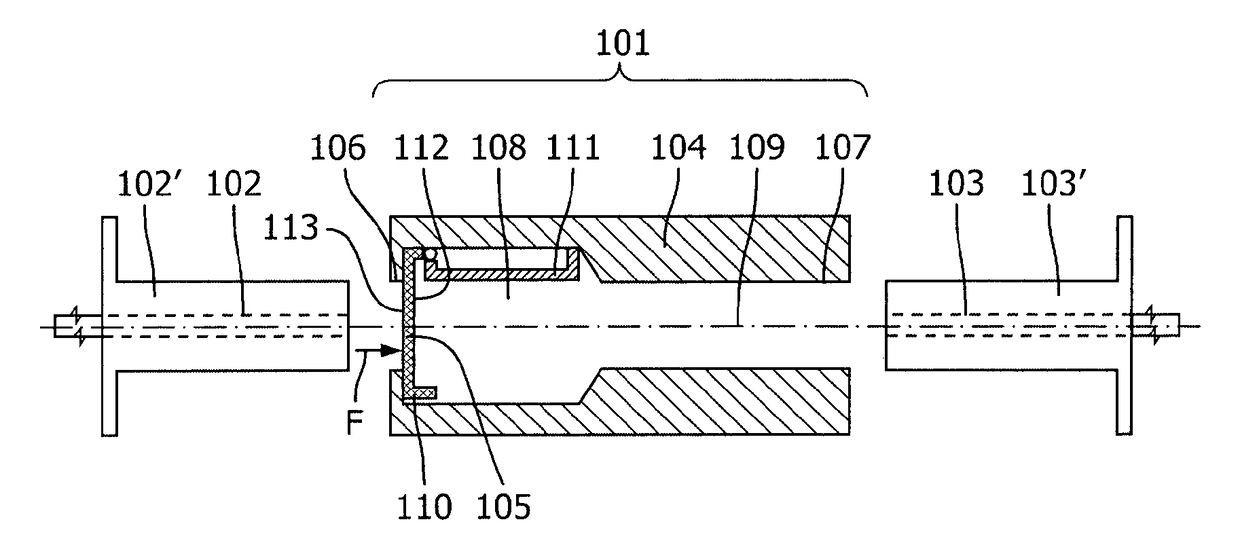
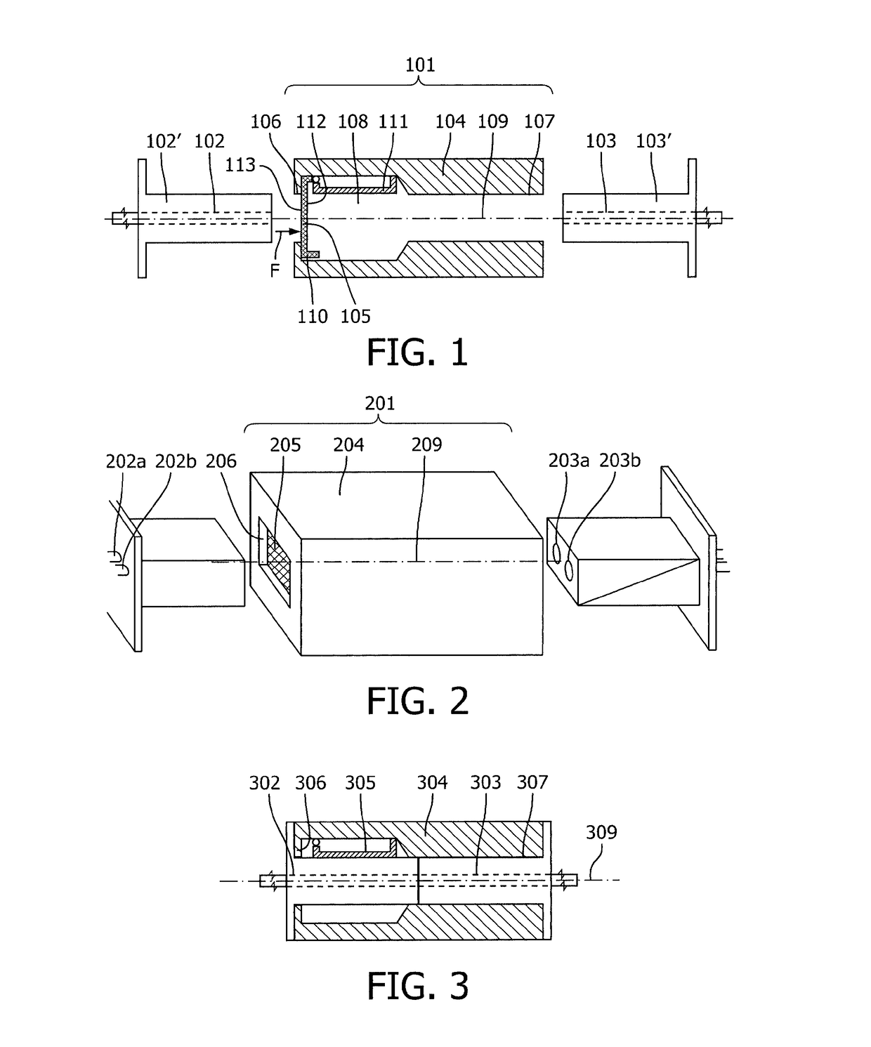
[0099]An optical fiber connector (101) for mating a first group of one or more optical fibers (102) with one or more corresponding optical fibers in a second group of one or more optical fibers (103); the optical fiber connector comprising a body (104) and a shutter (105);[0100]wherein the body (104) has a common axis (109), a cavity (108) disposed along the common axis (109), a first port (106) for receiving the first group of one or more optical fibers (102), and a second port (107) for receiving the second group of one or more optical fibers (103), wherein the first port (106) is at one end of the body (104) and extends along the common axis (109) into the cavity (108), and the second port (107) is at the opposite end of the body (104) and extends along the common axis (109) into the cavity (108);[0101]wherein the shutter (105) is hingeably mounted to the first port; the shutter being selectively movable between a closed state (110) in which the shutter blocks the firs...

2nd example

2nd Example

[0103]The optical fiber connector (101) according to Example 1 wherein the shutter (105) is movable between the closed state (110) and the open state such that the shutter is within the cavity in the open state (111).

3rd example

3rd Example

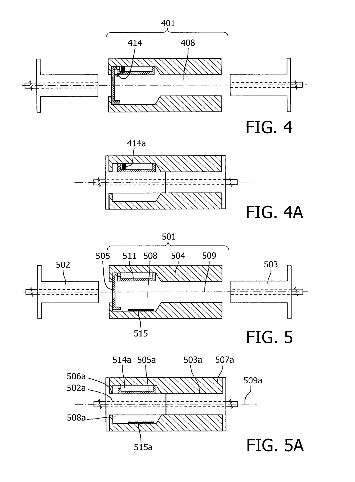
[0104]The optical fiber connector according to Example 2 further comprising mechanically resistive means (414), the mechanically resistive means being in mechanical communication with the shutter and the body; wherein the mechanically resistive means is configured to provide a restoring force to counteract movement of the shutter from the closed state towards the open state.


PUM

PropertyMeasurementUnit
wavelengthaaaaaaaaaa
spectral full width half maximumaaaaaaaaaa
reflectanceaaaaaaaaaa

Abstract

The present invention relates to an optical fiber connector for mating a first group of one or more optical fibers (102) with one or more corresponding optical fibers in a second group of one or more optical fibers (103). The optical fiber connector includes a shutter (105), which prevents the ingress of debris into the connector, and provides an optical reference surface with which to calibrate optical fibers that are inserted into the connector. The optical fiber connector finds application in the general optical fiber field, and more particularly finds application in the medical field in which it may be used to connect optical fibers in a photonic needle application.

Description

CROSS-REFERENCE TO PRIOR APPLICATIONS[0001]This application is the U.S. National Phase application under 35 U.S.C. § 371 of International Application No. PCT / EP2015 / 057435, filed on Apr. 7, 2015, which claims the benefit of U.S. Provisional Patent Application No. 61 / 980,164, filed Apr. 16, 2014, European Patent Application No. 14167748.4, filed May 9, 2014 and European Patent Application No. 14198423.7, filed on Dec. 17, 2014. These applications are hereby incorporated by reference.FIELD OF THE INVENTION[0002]The present invention relates to an optical fiber connector for interconnecting optical fibers. The invention also relates to the calibration of the optical path of an optical fiber. The optical fiber connector may be used in the general field of optical fibers, including the optical test and measurement field. More specifically the optical fiber connector finds application in the medical field wherein it may be used to calibrate optical fibers used in optical spectroscopy-base...

Claims


Application Information

Patent Timeline
Patent Type & Authority Patents(United States)
IPC IPC(8): G01N21/00G01N21/27G02B6/38
CPCG01N21/276G02B6/3825G02B6/3866G02B6/3885G02B6/3845G01N2201/084G02B6/3869G02B6/3849G01J3/0218A61B2562/146A61B2560/0223A61B5/0075A61B5/0071G01J3/0232G01J3/0297G01J2003/2866G01J3/28G01N21/278
Inventor WIJBRANS, KLAAS CORNELIS JANLUCASSEN, GERHARDUS WILHELMUSHENDRIKS, BERNARDUS HENDRIKUS WILHELMUSREICH, CHRISTIANVAN ROOIJ, JOHANNES ANTONIUSKNOESTER, JAAP
Owner KONINKLJIJKE PHILIPS NV
Why Eureka
Try Eureka