Torsional vibration damper

a torsional vibration and damper technology, applied in the direction of spring/damper, rotational vibration suppression, vibration suppression adjustment, etc., can solve the problems of generating undesirable impact noise in the tracks and the mass of the damper dropping, and achieve the effect of promoting elasticity

Active Publication Date: 2018-10-16
ZF FRIEDRICHSHAFEN AG
View PDF7 Cites 8 Cited by
  • Summary
  • Abstract
  • Description
  • Claims
  • Application Information

AI Technical Summary

Benefits of technology

[0007]It is an object of one embodiment of the invention to construct a torsional vibration damper provided with damper masses such that impact noise can be efficiently prevented even in operating phases in which the centrifugal force acting on the damper masses falls below the weight force.
[0010]Viewed in circumferential direction, the first contact region of the geometric shaping is preferably located between two second contact regions of the geometric shaping that adjoin at the circumferential end sides. The first contact region is formed of two parts for configuring mutually opposing working directions of the at least one damper mass, each shaping-half being adapted with respect to its shape to the shape of the corresponding profile stop of the associated stop, resulting in a particularly low-noise impact behavior when each shaping-half has, at its side facing the stop profile of the stop, a curvature shape adapted to a curvature shape of the stop profile of the stop.
[0015]As a further alternative, the stops can be floatingly received with respect to the stop receivers and are therefore movable relative to the stop receivers. When the stops are floatingly received, particularly when they are provided at an annular component part, they can have increased resiliency and, therefore, improved damping characteristics. This can have advantageous results when the damper mass elements engage by their stop sides.
[0017]In one embodiment, the spacers extend through the respective holder at the stop with an axial offset between the axis of the respective spacer and the axis of the respective holder. Owing to this axial offset, a free space results between the holder and the respective spacer. This free space promotes an elasticity at the stop in that the wall of the holder impinged by a damper mass can extend elastically into this free space. A solution of this kind is attractive when the radial stops for a plurality of damper masses are collectively arranged on a common, preferably annular, component part that extends radially inwardly of the damper masses and when the axial offset is so configured that the respective free spaces occur in the radially outer regions of the holders. The annular component part is then centered via the radially inner regions of the holders.

Problems solved by technology

As soon as the centrifugal force has dropped below the weight force, the damper masses drop down and generate an undesirable impact noise in their tracks and / or at the stops.

Method used


Image

  • Torsional vibration damper
  • Torsional vibration damper
  • Torsional vibration damper

Examples


Embodiment Construction

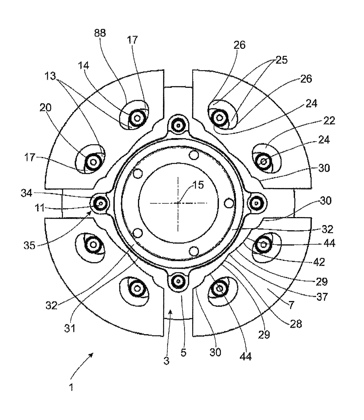
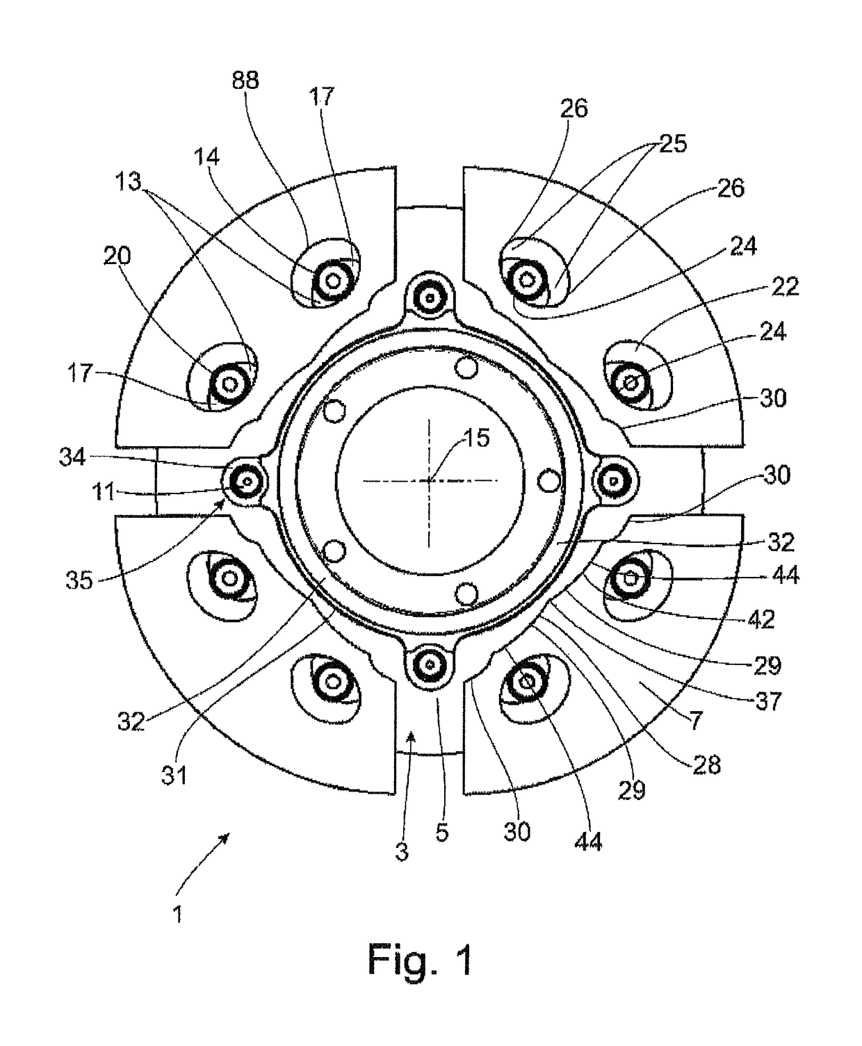
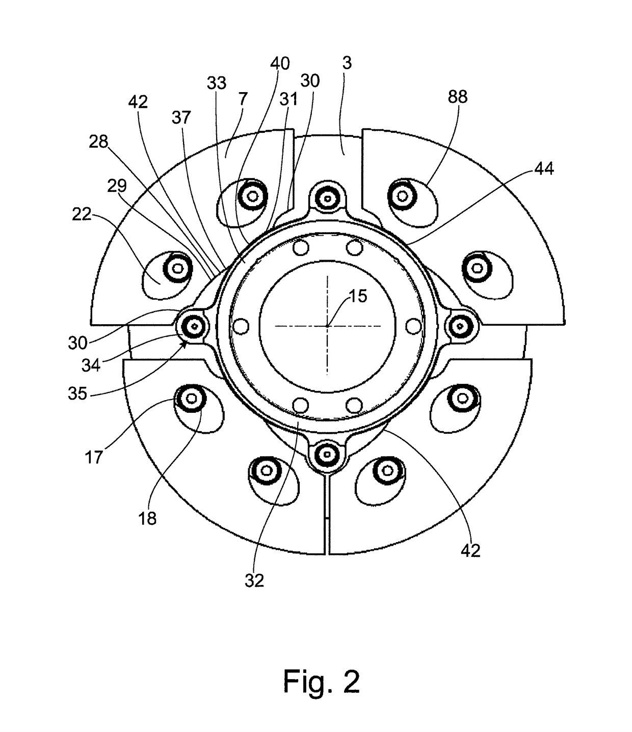
[0039]FIG. 1 shows a torsional vibration damper 1 with a damper mass carrier 3 that has two axially spaced damper mass support elements 5, of which only the damper mass support element 5 arranged axially behind the damper masses 7 is shown for the sake of a clearer illustration of a plurality of damper masses 7 received at the damper mass carrier 3. The two damper mass support elements 5 are connected to one another by spacers 11. The two damper mass support elements 5 and one of the spacers 11 are also shown in FIG. 9 or FIG. 10. The damper masses 7 are arranged over rolling bodies 20 inside guideways 22 (see FIG. 2), specifically in such a way that the guideways 22 allow a radial relative movement of the damper masses 7 with respect to the spacers 11. The damper masses have, at their radial inner sides, stop sides 42 that will be described more fully.

[0040]Guideways 13 are provided in pairs at the damper mass support elements 5 in each instance. Each guideway 13 extends in a curve...


PUM


Abstract

A torsional vibration damper has a damper mass carrier at which is received at least one damper mass movable relative to the damper mass carrier and with at least one stop. The at least one damper mass has a stop side with a geometric shaping. At least one stop is associated with the damper mass, and has an axial overlap with the at least one damper mass in extension direction of a central axis and a stop profile at its side facing the stop side of the damper mass. At least one stop receiver is associated with the least one stop for the at least one damper mass. The geometric shaping which is provided at the at least one damper mass has a first contact region operative at least substantially in radial direction and a second contact region operative at least substantially in tangential direction. The first contact region can be brought into operative connection with the stop, and the second contact region can be brought into operative connection with the stop receiver.

Description

CROSS REFERENCE TO RELATED APPLICATIONS[0001]This is a U.S. national stage of application No. PCT / EP2013 / 070306, filed on Sep. 30, 2013. Priority is claimed on German Application No.: DE102012219737.0, filed Oct. 29, 2012, the content of which is incorporated herein by reference.BACKGROUND OF THE INVENTION[0002]1. Field of the Invention[0003]The present invention is directed to a torsional vibration damper provided with a damper mass carrier at which is received at least one damper mass movable relative to the damper mass carrier and at least one stop. The at least one damper mass has a stop side with a geometric shaping and at least one stop is associated with the at least one damper mass. The stop has an at least partial axial overlap with the at least one damper mass in extension direction of a central axis and has, at its side facing the stop side of the damper mass, a stop profile. At least one stop receiver is associated with the least one stop for the at least one damper mass...

Claims


Application Information

Patent Timeline
Patent Type & Authority Patents(United States)
IPC IPC(8): F16F15/14
CPCF16F15/145Y10T74/2128
Inventor KRAM, MATTHIASSTAMPF, VOLKERSUDAU, JORGSASSE, CHRISTOPHSTURMER, ARMINWIRACHOWSKI, MICHAELDONG, YINGKOKOTT, FRIEDRICHPITTNER, DANIELANDRES, OLIVERVIERNEUSEL, SIMONEEGLER, DENNIS
Owner ZF FRIEDRICHSHAFEN AG
Why Eureka
Try Eureka