Thermal monitoring of a converter

a converter and thermal monitoring technology, applied in the direction of instruments, measurement devices, emergency protective arrangements, etc., can solve problems such as power loss, and achieve the effect of simple thermal models

Active Publication Date: 2018-10-16
View PDF40 Cites 1 Cited by
  • Summary
  • Abstract
  • Description
  • Claims
  • Application Information

AI Technical Summary

Benefits of technology

[0017]It is advantageous in this case if the measured start temperature occurs as a factor in the thermal model. A relatively simple thermal model thereby results.

Problems solved by technology

The power loss is then that power which is responsible for the heating of the converter.

Method used


Image

  • Thermal monitoring of a converter
  • Thermal monitoring of a converter

Examples


Embodiment Construction

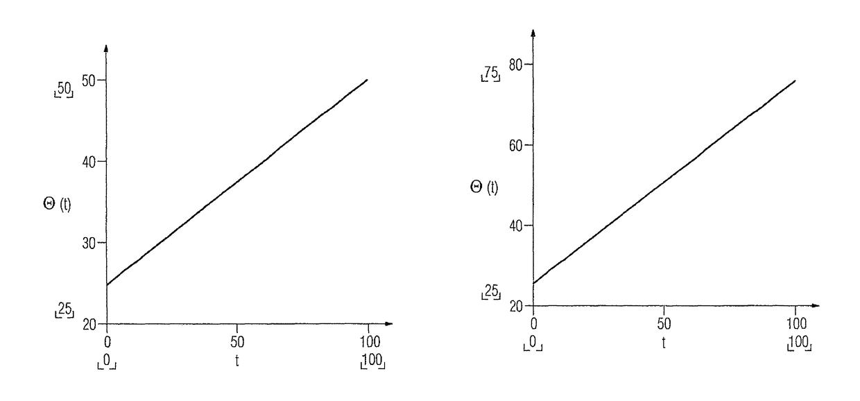
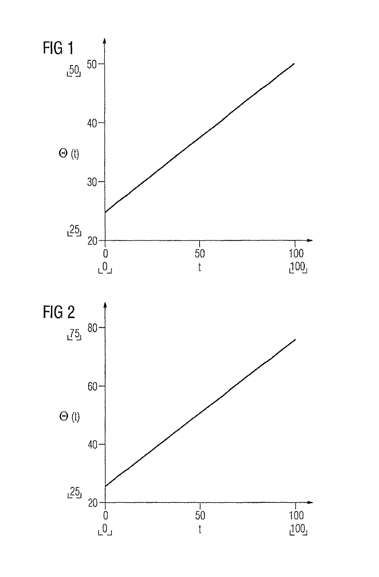
[0022]The thermal time constant, in other words that time in which the converter heats up by a predetermined temperature value, differs significantly with and without a functioning water cooling system. In the case of specified normal use, the time constant can be easily determined and stored in the converter or the monitoring system thereof. With the time constant, a thermal model of the converter temperature can be created.

[0023]An important factor of the thermal model is the power loss of the converter. The power loss is that power which is ultimately converted into heat in the converter. It can be determined according to the following formula:

Pv=(1−η)Pges

[0024]where η corresponds to the efficiency of the converter, in other words the quotient of output power and input power. Pges corresponds to the input power, in other words the total power flowing into the converter. Said power Pges can be calculated from the variables normally present for regulating the drive, such as interm...


PUM


Abstract

The thermal monitoring of a converter for an electric motor of a vehicle should be improved. Therefore, the invention relates to a method in which the temperature of the converter is measured. In addition, the output power of the converter is determined. The temperature of the converter is estimated using a thermal model of the converter having the output power as an input variable. The estimated temperature is compared with the measured temperature, and a corresponding monitoring signal is provided. Thus, a deviation of the measured temperature for the calculated temperature and thus a corresponding error in the cooling system can be detected even in the partial-load range.

Description

CROSS-REFERENCES TO RELATED APPLICATIONS[0001]This application is the U.S. National Stage of International Application No. PCT / EP2012 / 064385, filed Jul. 23, 2012, which designated the United States and has been published as International Publication No. WO 2013 / 014120 and which claims the priority of European Patent Application, Serial No. 11175544.3, filed Jul. 27 2011, pursuant to 35 U.S.C. 119(a)-(d).BACKGROUND OF THE INVENTION[0002]The present invention relates to a method for thermal monitoring of a converter for an electric motor of a vehicle, wherein the temperature of the converter is measured. The present invention furthermore relates to a monitoring device for thermal monitoring of the converter, having a measuring facility for measuring the temperature of the converter.[0003]Internal combustion engines in motor vehicles are usually cooled by a liquid cooling system. If this cooling system fails, then the temperature of the combustion engine rises as a function of the load...

Claims


Application Information

Patent Timeline
Patent Type & Authority Patents(United States)
IPC IPC(8): G01R31/00H02H6/00H02H7/122
CPCG01R31/006H02H6/005H02H7/122
Inventor KUHN, ANDREAS
Why Eureka
Try Eureka