Measurement and calculation method of turbine shaft system center

A steam turbine and shafting technology, which is applied in the field of measuring and calculating the center of steam turbine shafting, can solve the problems of reducing the efficiency of measuring and calculating the center of steam turbine shafting, reducing the speed of measuring and calculating the center of steam turbine shafting, and the direction of numerical value is prone to errors, so as to reduce the amount of measurement and calculation. Possibility of mistakes, fast calculation speed, and the effect of improving efficiency

Active Publication Date: 2016-08-31
DATANG SHANDONG ELECTRIC POWER OVERHAUL & OPERATION
View PDF2 Cites 1 Cited by
  • Summary
  • Abstract
  • Description
  • Claims
  • Application Information

AI Technical Summary

Problems solved by technology

[0008] For the shafting center of a multi-rotor steam turbine, the calculation method is similar to that of the two-rotor coupling center, but the influence of one rotor adjustment on the circumference and opening of the next back wheel needs to be fully considered in the calculation, and the calculation workload is relatively large, such as figure 2 , after calculating the adjustments of #3 and #4 bearings, the values ​​of the opening and circumference of rotors 2 and 3 will change. These values ​​will not be re-measured separately in the actual field. Generally, the adjustment of #3 and #4 bearings to 2 will be recalculated. , No. 3 rotor opening, and the influence value of the circumference value, combined with the o

Method used


Image

  • Measurement and calculation method of turbine shaft system center
  • Measurement and calculation method of turbine shaft system center
  • Measurement and calculation method of turbine shaft system center

Examples


Embodiment Construction

[0037] The present invention will be further described below in conjunction with accompanying drawing.

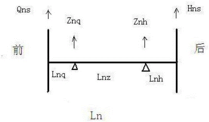
[0038] 1. Establish a measurement model

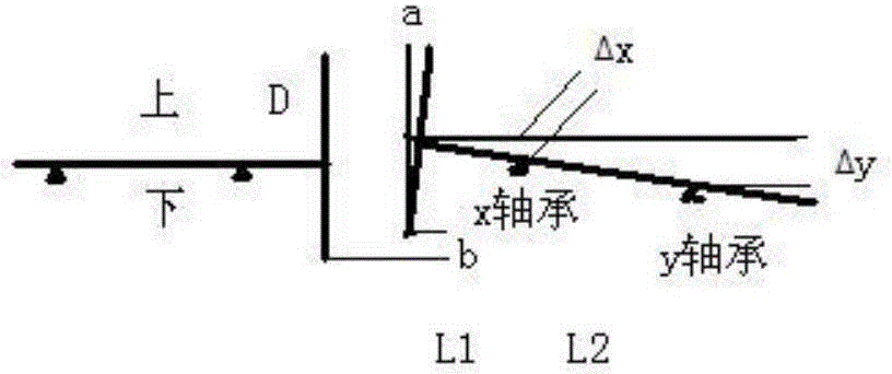
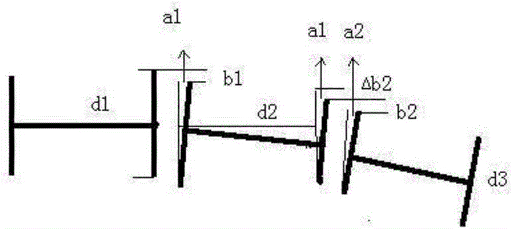
[0039] In the process of calculating and adjusting the center of the shaft system, there is a frequently used value, which is the adjustment amount of the backrest wheel during the adjustment process. For a certain rotor, the adjustments of the two bearings can be calculated under the condition that the adjustments of the back wheels at both ends of the rotor are determined. And the adjustment amount of the backrest wheel can be calculated simply and conveniently according to the circumference and opening of the backrest wheel.

[0040] For the convenience of calculation, first establish a calculation model:

[0041] (1) All rotors are rigid bodies, and there is no deformation due to gravity, rotation and other factors;

[0042] (2) The centerline of the rotor is a straight line, the cross-section of any part is a circle with the...


PUM


Abstract

The invention discloses a measurement and calculation method of a turbine shaft system center. The measurement and calculation method comprises the following steps: firstly, carrying out modeling on a turbine shaft system before repair, and measuring the center number value of the turbine shaft system before repair, the length of each rotor and the diameter of the rear clutch of each rotor to obtain the modeling data of the turbine shaft system before repair; then, according to the modeling data of the turbine shaft system before repair, calculating the adjustment amount of each rotor clutch; and taking the adjustment amount of each rotor clutch as an intermediate value to calculate to obtain the adjustment amount of a corresponding rotor bearing so as to calculate the adjustment amount of a corresponding bearing regulation spacer according to the adjustment amount of each bearing and the position of each adjustment spacer. Firstly, the center number value of the turbine shaft system before repair is measured, the adjustment amount of each rotor clutch is calculated, the adjustment amount of each rotor clutch is taken as the intermediate value to calculate the adjustment amount of the corresponding bearing, an influence value on a rear clutch opening value after the rotor bearing is regulated does not need to be measured and calculated, measurement and calculation can be well organized, and a measurement and calculation amount and measurement fault possibility are effectively reduced.

Description

technical field [0001] The invention relates to a method for measuring and calculating the shafting center of a steam turbine. Background technique [0002] During the operation of the steam turbine, the center of the steam turbine will change due to the wear of the supporting bearing, the displacement of the cylinder and the bearing seat, and the corrosion of the bearing pad iron. If the center changes too much, the vibration will exceed the standard, the moving and static parts will rub against each other, and the bearing will heat up. Therefore, during the overhaul of the turbogenerator set, it is necessary to check and adjust the center of each back wheel of the shafting. Multi-rotor steam turbine shaft center measurement is a very complicated task. The influence of rotor bearing adjustment on the opening and circumference of the center of the backrest wheel must be considered during calculation. The calculation is large and the value is very easy to make mistakes. A w...

Claims


Application Information

Patent Timeline
IPC IPC(8): G06F19/00
CPCG16Z99/00
Inventor 尉帅李继强王俊滨
Owner DATANG SHANDONG ELECTRIC POWER OVERHAUL & OPERATION
Why Eureka
Try Eureka