Systems and methods for self-standing, self-supporting, rapid-deployment, movable communications towers

a technology of self-supporting, movable communications towers, applied in the direction of towers, antennas, buildings, etc., can solve the problems of inconvenient placement of communications towers on private property, large foundation and ground work, and inconvenient construction, so as to reduce the need for building permits, and be flexible

Inactive Publication Date: 2018-10-23
ADAPTIVE COMM LLC
View PDF16 Cites 0 Cited by
  • Summary
  • Abstract
  • Description
  • Claims
  • Application Information

AI Technical Summary

Benefits of technology

[0024]One advantage of the present invention is in in the self-standing, self-supporting nature of the communications towers provided. Such towers can also be deployed rapidly and repositioned on short notice, as may be desirable in, for example, emergencies such as natural disasters, and as a result may be considered self-standing, self-supporting, rapid-deployable (S4RD) communications towers. Communications towers of the present invention thus provide a flexible, cost-effective option for providing carrier grade telecommunications systems.
[0025]Ballast base systems of the present invention generally require no site excavation, foundation forming, rebar work, or concrete pouring; the most ground work that is required is placement of a surface layer of gravel or road base if the underlying ground is soggy or unstable. The ballast base system enables towers to be placed on ground with at least some degree of unevenness; generally, about 3 inches' difference between maximum and minimum height is permissible. As a result of the simple and non-permanent installation allowed by the ballast base system, the need for building permits is often eliminated or reduced.
[0026]Towers, including communications towers, of the present invention alleviate the need to invest significant time and money in the construction of a permanent tower foundation that prevents the tower from being moved or used at another location, and are much more feasible for installation on rugged or remote terrain. Additionally, communications towers of the present invention may be deployed to a desired location in a matter of minutes or hours, generally without the need to obtain building permits or utilize heavy excavation or construction equipment. By way of non-limiting example, communications towers of the present invention may be disassembled at one location, loaded onto a standard-size flatbed trailer or similar towing or transportation means, transported to a second location, and reassembled in the space of several hours or a day.

Problems solved by technology

Despite the need for expansion of wireless networks, particularly in rural areas, conventional communications towers continue to suffer from several drawbacks that make their placement on private property impractical.
Towers of the prior art require extensive foundation and ground work, including the excavation of numerous large holes and the placement of significant quantities of rebar and / or concrete, which is undesirable to many property owners who would prefer not to erect such a significant and permanent foundation.
A permanent foundation may be especially undesirable when the need for the communications tower is temporary and / or when it may be advantageous for the tower to be moved rapidly or frequently, such as in the cases of, by way of non-limiting example, natural disasters or other emergencies, military operations, and sporting events.
Attempts to overcome these obstacles have largely focused on lower-end self-standing or guyed towers with lesser foundation requirements, but such towers suffer from additional drawbacks.
As a result, such towers are difficult for a technician to climb to place antennas.
Moreover, such small towers lack rigidity and so may move or twist due to wind and ground disturbances; the point-to-point backhaul antennas typical of many communications networks utilize very narrow radio beams and so require extremely precise placement, and as a result the shifting, twisting, or movement of the towers on which the antennas are mounted may significantly degrade bandwidth and network performance.
In addition, when the tower is subjected to wind or another extrinsic bending load, the entire load is transmitted to the base at a single connection point, requiring a very heavy base to prevent the connection between the tower and the base from breaking.

Method used


Image

  • Systems and methods for self-standing, self-supporting, rapid-deployment, movable communications towers
  • Systems and methods for self-standing, self-supporting, rapid-deployment, movable communications towers
  • Systems and methods for self-standing, self-supporting, rapid-deployment, movable communications towers

Examples


Embodiment Construction

[0036]The ensuing description provides embodiments only, and is not intended to limit the scope, applicability, or configuration of the claims. Rather, the ensuing description will provide those skilled in the art with an enabling description for implementing the embodiments. It should be understood that various changes may be made in the function and arrangement of elements without departing from the spirit and scope of the appended claims.

[0037]As used herein, the term “backhaul” refers to that portion of a telecommunications network that provides an intermediate link between a core or backbone network and an edge subnetwork or user.

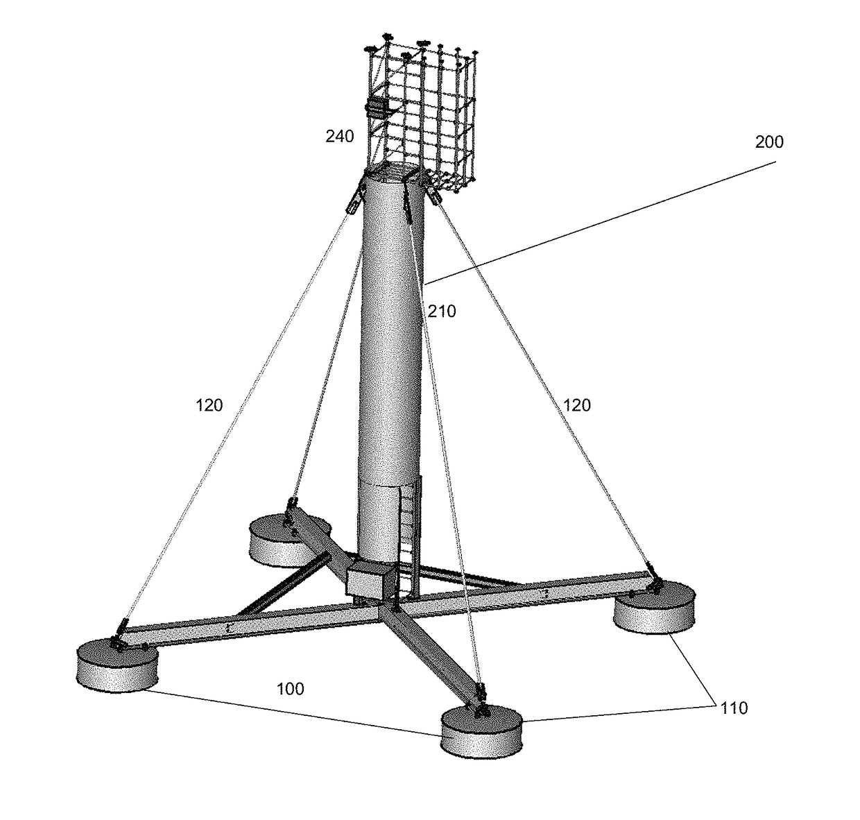
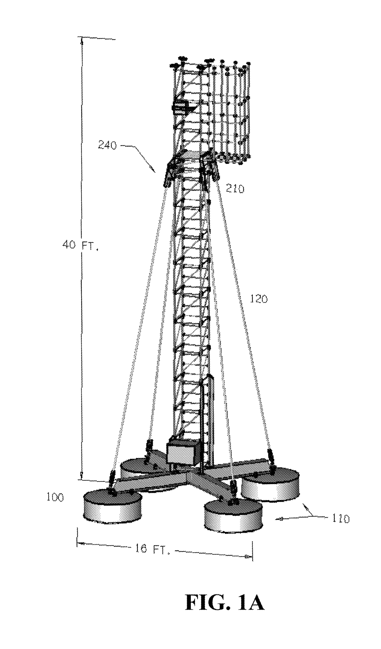
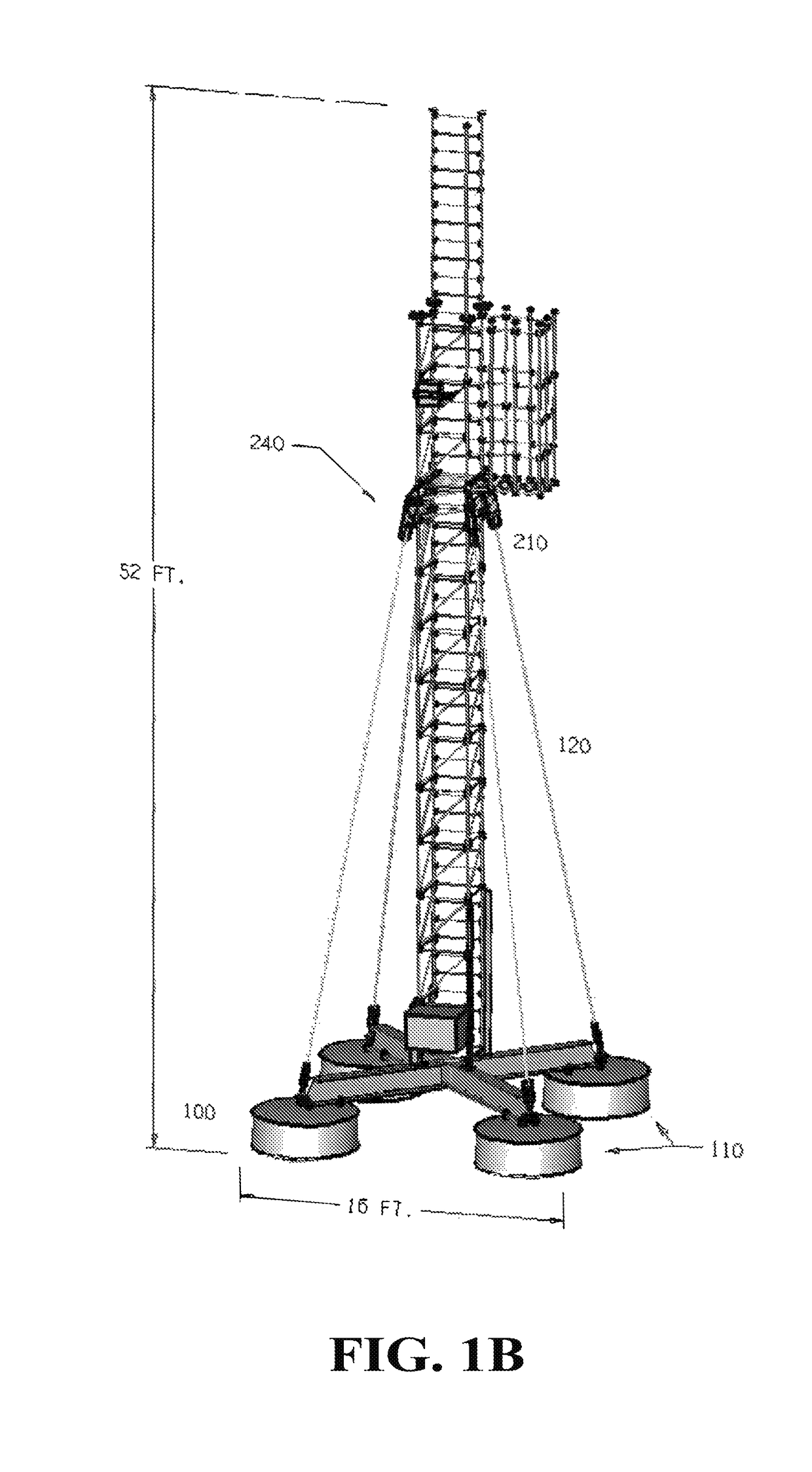
[0038]As used herein, the term “ballast base” refers to any base for a tower that includes sufficient ballast or weight, and is held stationary at a sufficient distance from the tower, to provide support to the tower to enable the tower to be self-supporting. A ballast base provides structural support to a tower sufficient to provide a pre-load onto th...


PUM


Abstract

The present disclosure relates to systems and methods for providing self-standing, self-supporting, rapid-deployable (S4RD) towers for communications and similar applications, and in particular to ballast base systems that enable the self-standing, self-supporting, rapid-deployable features while eliminating the need for a permanent foundation for the tower. Novel and inventive tower designs, wherein a user may climb through an interior volume of the tower while using the tower structure as both ladder and man cage, are also disclosed.

Description

FIELD OF THE INVENTION[0001]The present invention is generally directed toward systems and methods for providing communications towers, and particularly directed toward communications towers that are self-standing, self-supporting, movable, and capable of being deployed rapidly.BACKGROUND OF THE INVENTION[0002]As wireless networks for a wide variety of applications continue to grow and expand, the identification of suitable locations for new communications towers is becoming increasingly important. Often, the most suitable locations are on private property, especially in the case of wireless Internet and telephone networks in rural areas, where communications towers on, for example, farm or ranch land may be necessary or desirable.[0003]Despite the need for expansion of wireless networks, particularly in rural areas, conventional communications towers continue to suffer from several drawbacks that make their placement on private property impractical. Towers of the prior art require ...

Claims


Application Information

Patent Timeline
Patent Type & Authority Patents(United States)
IPC IPC(8): E04H12/20E04H12/10E04H12/34E04H12/18E04H12/00
CPCE04H12/20E04H12/10E04H12/34E04H12/18E04H2012/006E04H12/08E04H12/345H01Q1/005H01Q1/1242H01Q1/246
Inventor HARMER, TRACY DAVID
Owner ADAPTIVE COMM LLC
Why Eureka
Try Eureka