
Conveyor and method of producing a conveyor

a conveyor and conveyor technology, applied in the field of conveyors, can solve the problems of less suitable conveyors and cumbersome disassembly and reassembling of conveyors, and achieve the effects of reducing manufacturing costs, improving flexibility of belt and chain link conveyors, and cost saving

Active Publication Date: 2017-01-31
JONGE POERINK CONVEYORS
View PDF15 Cites 1 Cited by
  • Summary
  • Abstract
  • Description
  • Claims
  • Application Information

AI Technical Summary

Benefits of technology

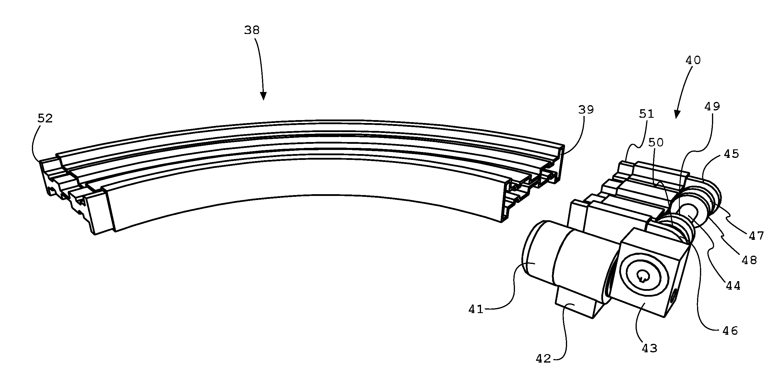
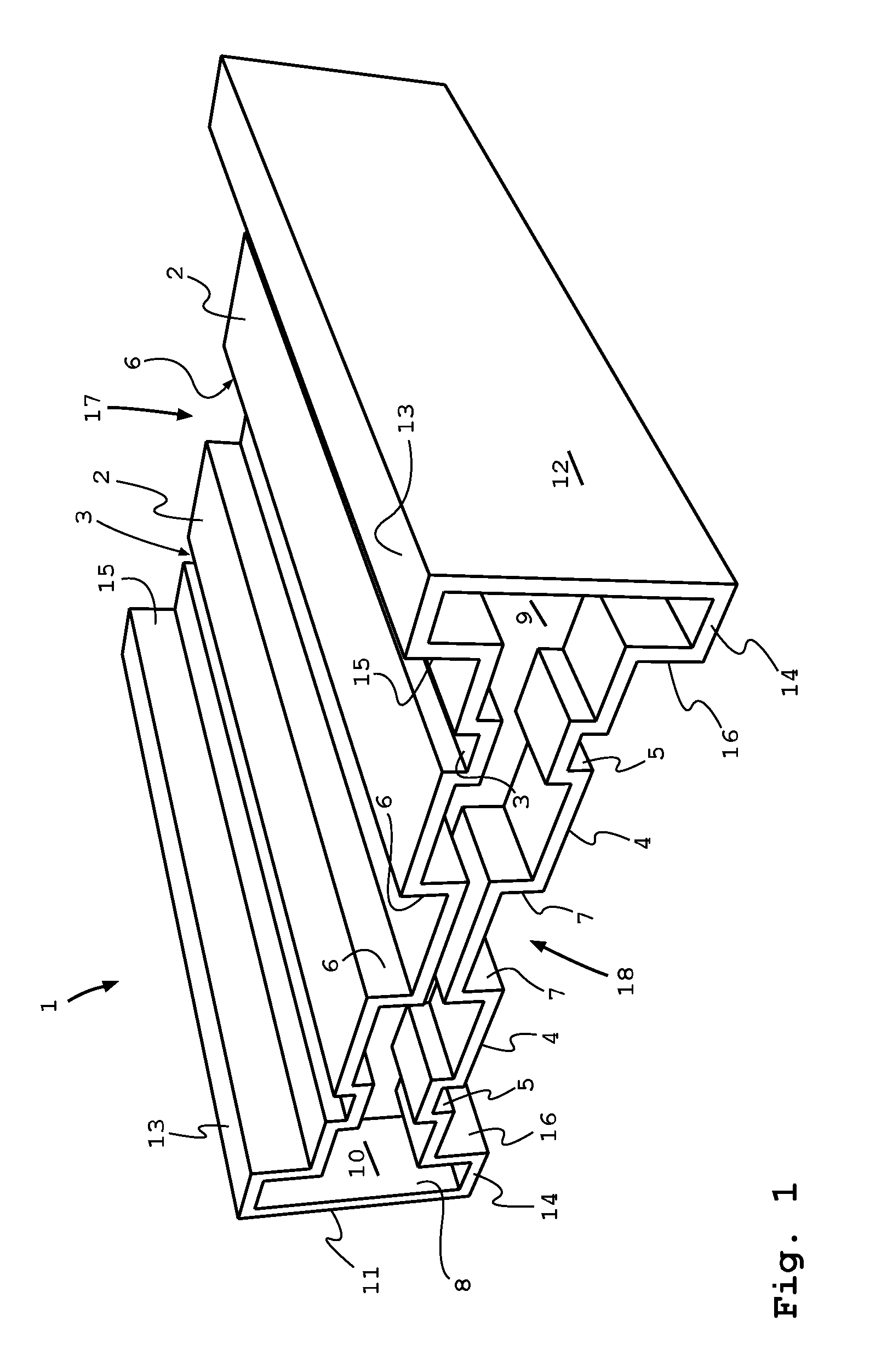
The invention provides a conveyor system that uses a rotary molded track structure, which is cost-effective and versatile. The conveyor track has a central guiding slit for rollers and can be connected to other track parts easily. It also includes slide bar connectors that provide additional strength and prevent wear on the support surface. The conveyor part can be interconnected to create a flexible and versatile system. Additionally, the invention includes a shaft or axle for guiding the belt or chain return, which can be connected to a drive. This design allows for a closed loop over the conveyor assembly. The invention provides a solution for better transport of the conveyor chain or belt.

Problems solved by technology

For less demanding applications and higher flexibility, e.g. when product pathways are changed frequently, conveyors of the art are less suitable.
Furthermore, they are more cumbersome to disassemble and reassemble.

Method used


Image

  • Conveyor and method of producing a conveyor
  • Conveyor and method of producing a conveyor
  • Conveyor and method of producing a conveyor

Examples


Embodiment Construction

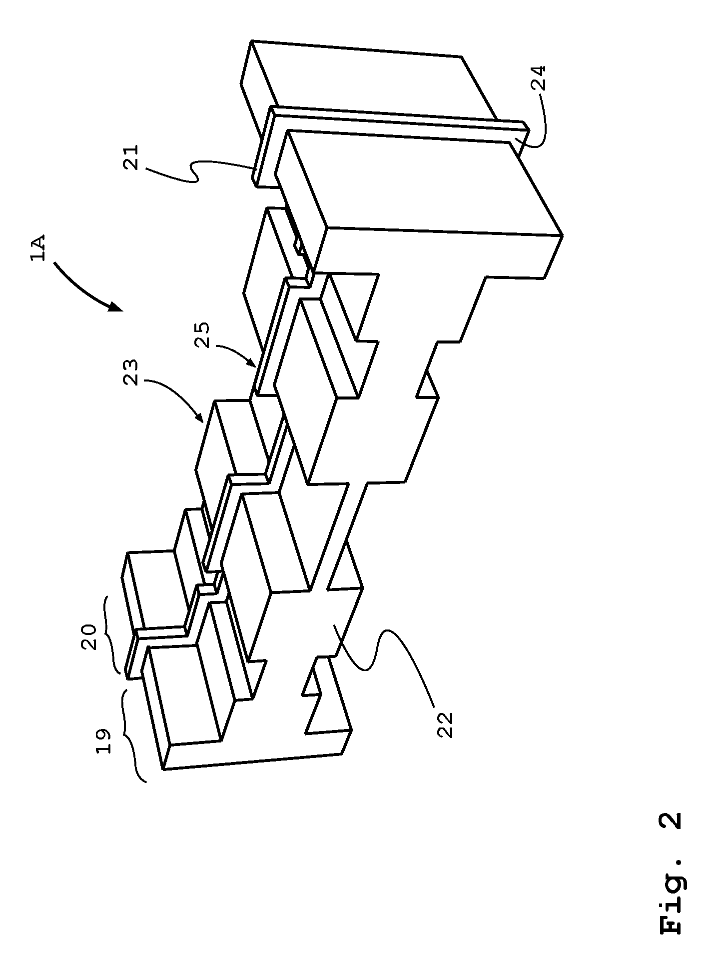
[0028]The figures represent specific exemplary embodiments of the inventions and should not be considered limiting the invention in any way or form. Throughout the description and the figures the same or corresponding reference numerals are used for the same or corresponding elements.

[0029]The expression “longitudinal” used herein is to be understood as, though not to be considered limited to the direction similar to the direction of motion of the belt or conveyor chain links within the conveyor track.

[0030]The expression “abutting end or abutting surface” used herein is to be understood as, though not to be considered limited to the ends of the conveyor track portion, where the track portion is connected to another track portion.

[0031]The expression “female or female connector of a track portion” used herein is to be understood as, though not to be considered limited to a connector configured to have an open structure able and suitable for accepting a male connector of a track port...


PUM

PropertyMeasurementUnit
angleaaaaaaaaaa
flexibleaaaaaaaaaa
flexibilityaaaaaaaaaa

Abstract

The invention relates to a conveyor part, having a conveyor track, wherein the conveyor track comprises at least one rotary moulded conveyor track structure. The invention further relates to a method of manufacturing a conveyor part comprising the following steps, to be performed in any suitable order: providing a rotary mould having a cavity shaped as the outside of a conveyor portions, adding a thermoplastic or resinous material inside the mould, rotating the mould under gradually heating the mould, allowing the thermoplastic material to melt and to cover the inner walls of the mould or allowing the resinous material to cure on the inner walls of the mould, allowing the mould to cool, opening the mould to remove the conveyor part.

Description

CROSS-REFERENCE TO RELATED APPLICATIONS[0001]This application is the United States national phase of International Application No. PCT / NL2014 / 050039 filed Jan. 24, 2014, and claims priority to Netherlands Patent Application No. 2010186 filed Jan. 25, 2013, the disclosures of which are hereby incorporated in their entirety by reference.BACKGROUND OF THE INVENTION[0002]Field of the Invention[0003]The invention relates to a conveyor.[0004]More specifically, the invention relates to more flexible and less expensive conveyor systems and to a method of their manufacture.[0005]Description of Related Art[0006]In the art, conveyor systems are widely used. Mostly a conveyor comprises some basic components: a support frame, a chain or belt track, a belt or chain, a drive system end and a belt or chain return end.[0007]In the art the conveyor track is manufactured of metal parts e.g. extruded aluminium elements, which are bolted or welded together. This provides a sturdy, yet rather heavy and i...

Claims


Application Information

Patent Timeline
Patent Type & Authority Patents(United States)
IPC IPC(8): B65G21/06B65G21/10B29D29/06B65G15/62B65G21/20B65G41/00B29K101/12
CPCB65G21/06B29D29/06B65G15/62B65G21/105B65G21/20B65G41/006B29K2101/12
Inventor OUDE ROELINK, ANTHONIUS GERHARDUS
Owner JONGE POERINK CONVEYORS
Learn More