Hydraulic damper with a hydraulic stop arrangement

a technology of hydraulic stop and damper, which is applied in the direction of shock absorbers, vibration dampers, springs/dampers, etc., can solve the problems of excessive abruptness, increased damping force in such solutions, and high risk of generating excessive damping forces, so as to achieve wide range of force tuning and easy configuration

Active Publication Date: 2018-10-23
BEIJING WEST IND CO LTD
View PDF30 Cites 11 Cited by
  • Summary
  • Abstract
  • Description
  • Claims
  • Application Information

AI Technical Summary

Benefits of technology

[0010]According to another aspect of the disclosure, a plurality of annular seats each extend axially from the axial projection and surround one of the axial slots. The annular seats reduce the pressure area working at the spring seat and in turn allow for employing a spring that has a low stiffness.
[0015]It should be appreciated that the aforementioned aspects simplify the construction of the subject hydraulic damper, particularly the components associated with the secondary piston assembly.
[0019]The hydraulic damper according to the present invention may easily be configured to generate additional damping force both for compression and rebound strokes enabling for wide range tuning of the force gains, wherein the performance of the arrangement may depend both on the piston position as well as on the piston velocity. The secondary piston may be easily configured to activate at the certain pressure activation threshold and thus function as a blow off safety valve.

Problems solved by technology

The increase of a damping force in such solutions may, in certain cases, be excessively abrupt.
Although such a progressive characteristic is advantageous, it also generates a high risk of generating excessive damping forces which may induce extremely high loads to various damper components (in particular components of the hydraulic stop arrangement itself) and other structural vehicle components which may be damaged.

Method used


Image

  • Hydraulic damper with a hydraulic stop arrangement
  • Hydraulic damper with a hydraulic stop arrangement
  • Hydraulic damper with a hydraulic stop arrangement

Examples


Embodiment Construction

[0035]Reference numerals to functionally equivalent elements remain the same on all figures of the drawing, wherein where appropriate, they are supplemented with additional suffixes (a, b) to differentiate elements of the same functionality but different construction.

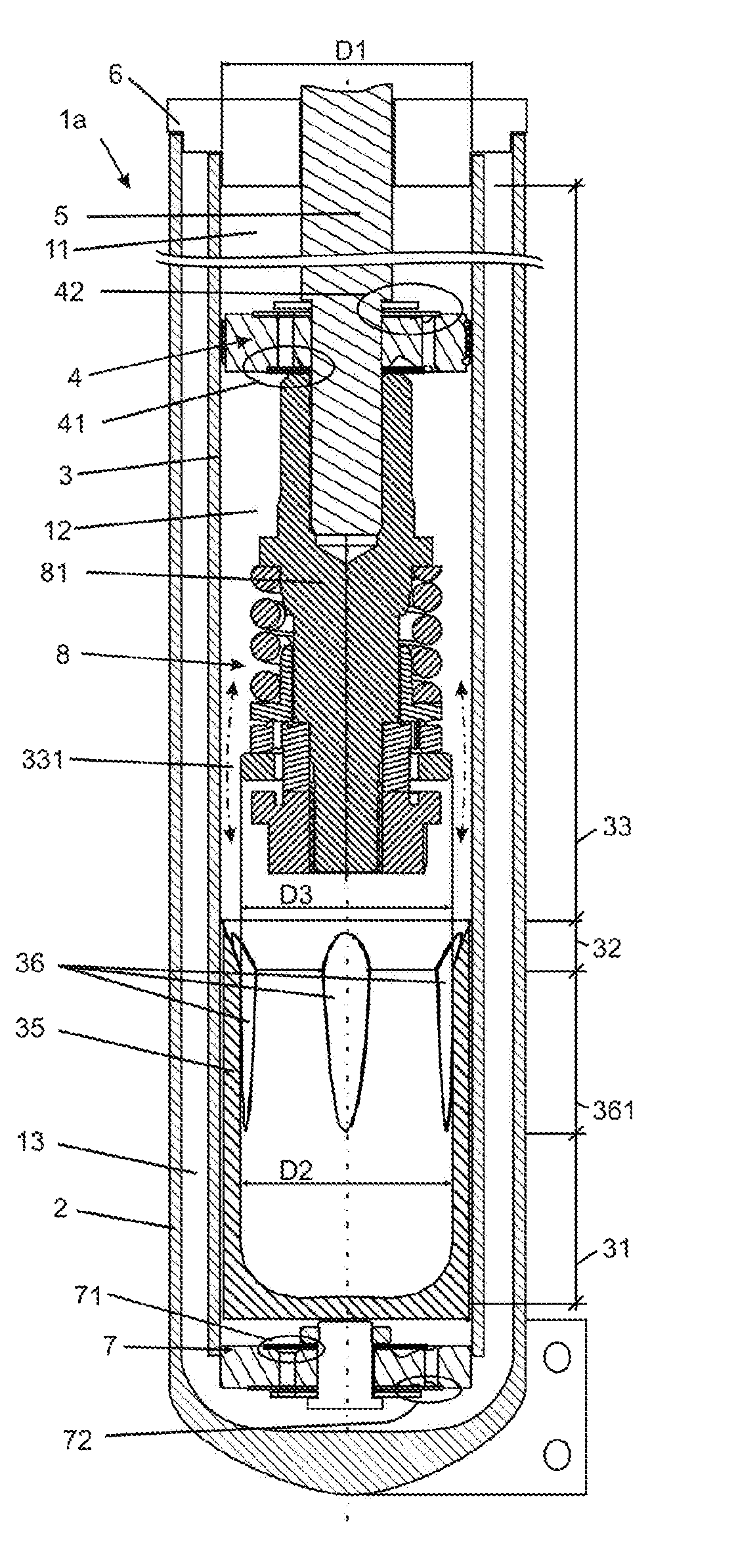
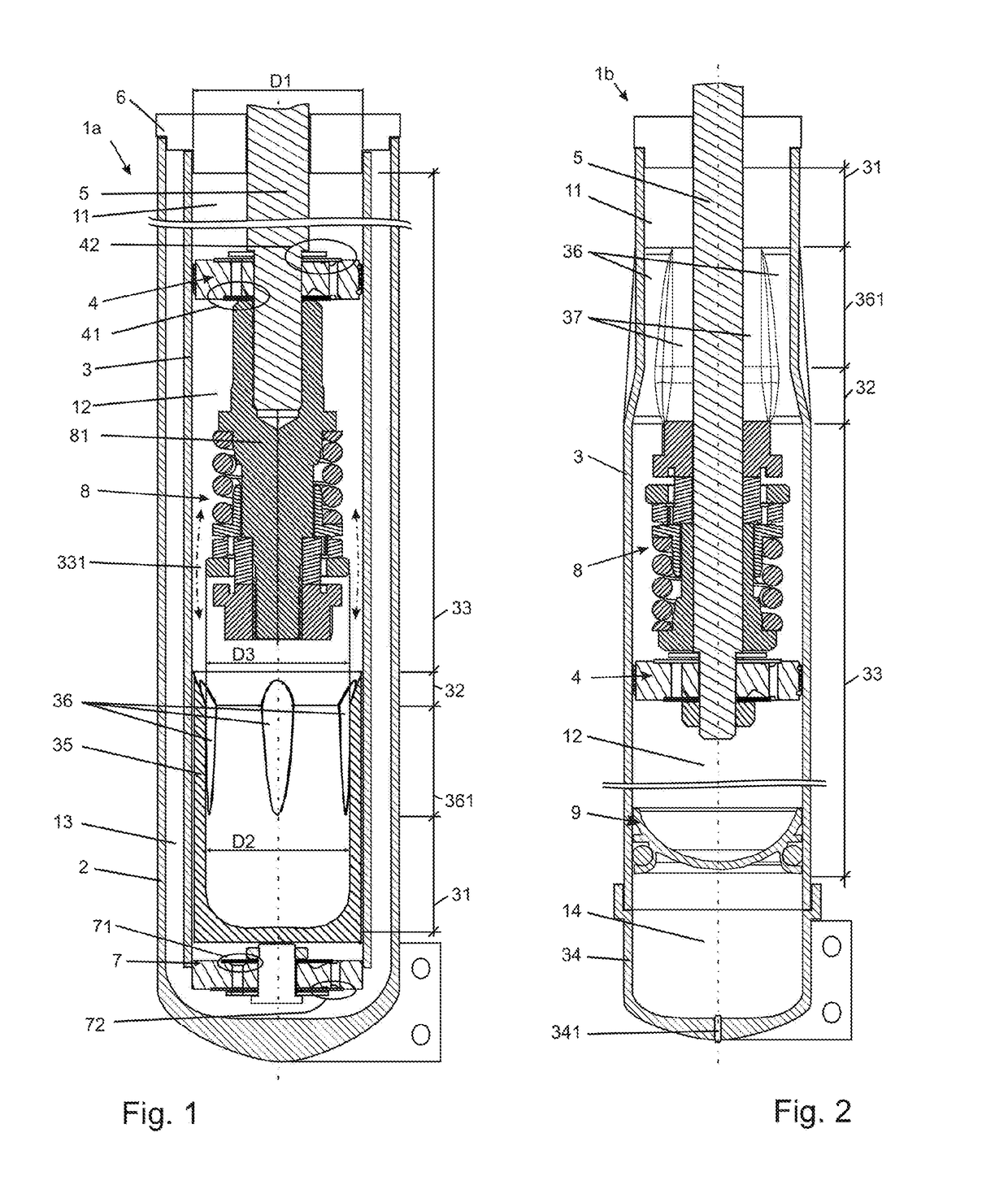
[0036]FIG. 1 presents an embodiment of a twin-tube damper la according to the present invention that may be employed in a typical motor vehicle suspension. The damper 1a comprises an external tube 2 and a main tube 3 filled with viscous working liquid. A movable main piston assembly 4 is disposed in the main tube 3. The main piston assembly 4 is attached to a main piston rod 5 led outside the damper la through a sealed piston rod guide 6. The damper la is also provided with a base valve assembly 7 fixed at the other end of the main tube 3. The main piston assembly 4 is slideably positioned against the inner surface of the main tube 3 and divides the tube 3 into a rebound chamber 11 (above the main piston assembly 4) and...


PUM


Abstract

A hydraulic damper for a motor vehicle including a tube having a main section and a narrowed section. A main piston assembly is disposed inside the main section. A main piston rod is attached to the main piston assembly. A secondary rod is coupled with the main piston rod. A spring seat is disposed about the secondary rod. A spring engages the spring seat and preloads the spring seat. A secondary piston is disposed about and coupled with the secondary rod. The secondary piston has an axial projection and an annular projection that abuts the spring seat. The annular projection defines a plurality of axial slots. A retaining member is fixed to the secondary rod and has an outer face defining a plurality of radial slots. A sealing ring is slidably disposed about the axial projection. An annular channel is defined radially between the sealing ring and the axial projection.

Description

CROSS REFERENCE TO RELATED APPLICATION[0001]This application claims the benefit of U.S. Provisional Patent Application Ser. No. 62 / 329,517 filed on Apr. 29, 2016, and titled “HYDRAULIC DAMPER WITH A HYDRAULIC STOP ARRANGEMENT”, the entire disclosure of which is hereby incorporated by reference.TECHNICAL FIELD[0002]The invention relates to a hydraulic damper for a vehicle. More particularly, the invention relates to a hydraulic damper for a vehicle including a main piston assembly and a secondary piston assembly.BACKGROUND OF THE INVENTION[0003]It is known in the art for hydraulic dampers to include a main piston assembly in a main section of a tube of the damper, and a secondary piston assembly in a narrowed section of the tube. The secondary piston assembly forms a so called hydraulic stop arrangement that generates additional damping force over a predefined end section of an operating range of piston rod travel. Exemplary dampers provided with such a hydraulic stop arrangements ar...

Claims


Application Information

Patent Timeline
Patent Type & Authority Patents(United States)
IPC IPC(8): F16F9/32F16F9/58F16F9/348
CPCF16F9/585F16F9/3482F16F9/3257F16F9/3221F16F9/3214F16F9/34F16F9/49
Inventor GRZESIK, RADOSLAW PAWELFLACHT, PIOTR ANDRZEJ
Owner BEIJING WEST IND CO LTD
Why Eureka
Try Eureka