Connector assembly for stacked electric power modules

a technology of connecting assembly and power module, which is applied in the direction of cell components, electrical apparatus casings/cabinets/drawers, coupling device connections, etc., can solve the problems of high frame material cost, difficult disassembly and maintenance, and difficult assembling, so as to achieve easy operation, simple connection structure, and easy operation.

Inactive Publication Date: 2018-10-23
FORMOSA ELECTRONICS IND INC
View PDF17 Cites 15 Cited by
  • Summary
  • Abstract
  • Description
  • Claims
  • Application Information

AI Technical Summary

Benefits of technology

[0004]An objective of the present invention is to provide a connector assembly for stacked electric power modules, which allows multiple electric power modules to achieve connection of power and signal among stacked and combined electric power modules through simple connection structure and easy operation.
[0006]The connector assembly for stacked electric power modules according to the present invention allows multiple electric power modules to achieve power and signal connection among the electric power modules that are stacked and combined together through a simple connection structure and an easy operation, without the need for complicated external plugging devices and connection sockets and also without complicated external connection cables, so that issues of time and cost required for manual assembling and reliance on skilled operator can be completely eliminated and also, issues of poor visual perception, difficult maintenance, and safety resulting from disorderly exposure of cables / lines on the back side of the electric power module can be overcome.

Problems solved by technology

Such a conventional arrangement has several drawbacks, such as being hard to assemble, being difficult to disassemble and maintain, and high material costs for the frame.
This operation causes a great waste of labor cost of assembly and generally relies on skilled operators.
In addition, the cables are located on the back side of the electric power modules in a disordered and messy manner, leading to poor visual perception and difficulty of maintenance, and also causing security and safety issues.

Method used


Image

  • Connector assembly for stacked electric power modules
  • Connector assembly for stacked electric power modules
  • Connector assembly for stacked electric power modules

Examples


Embodiment Construction

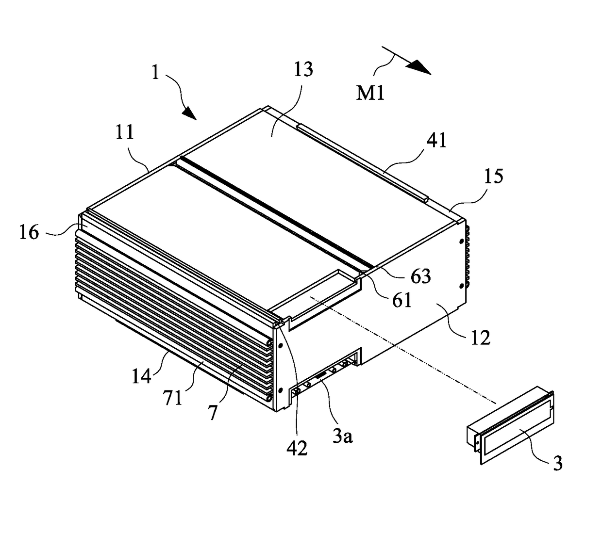
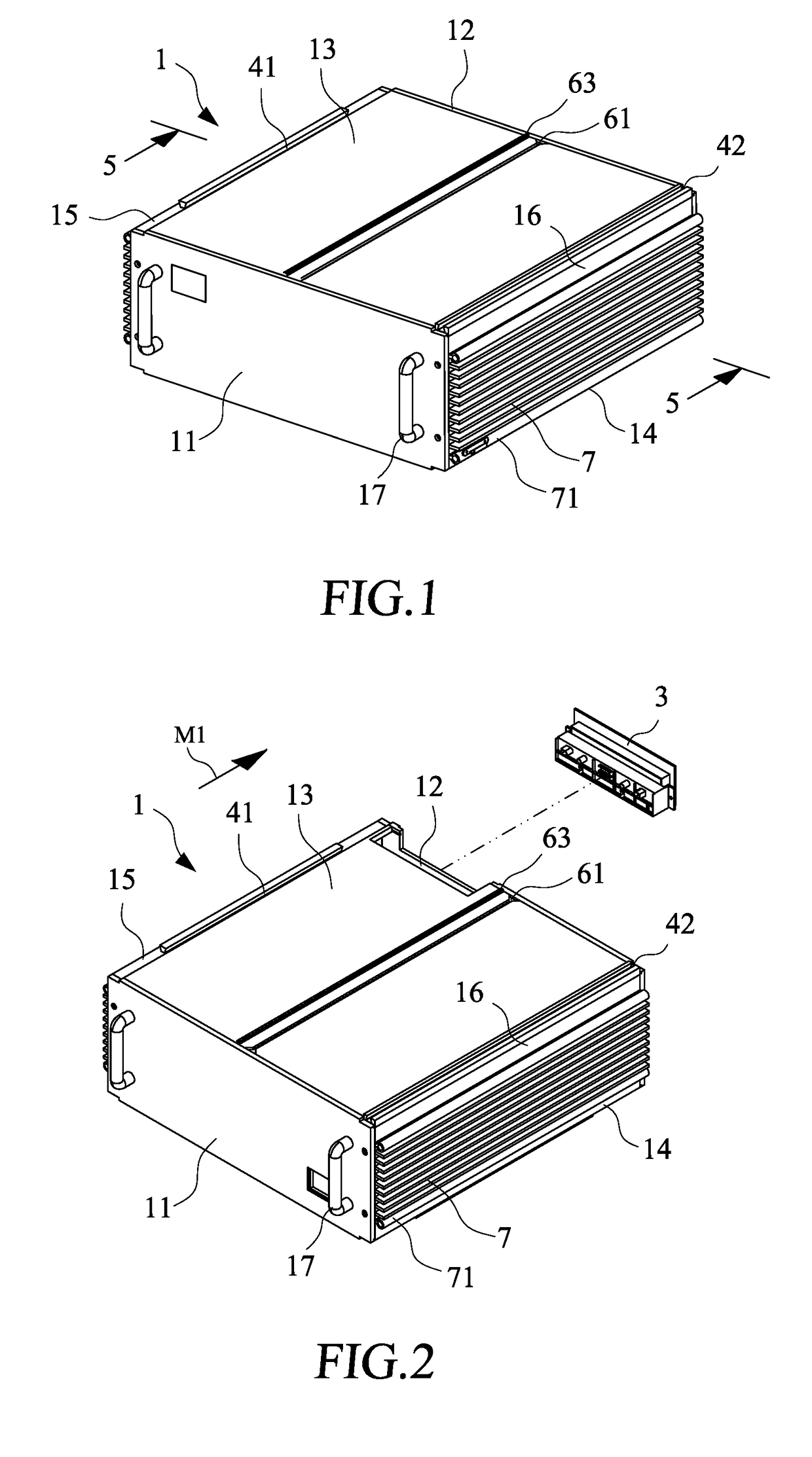
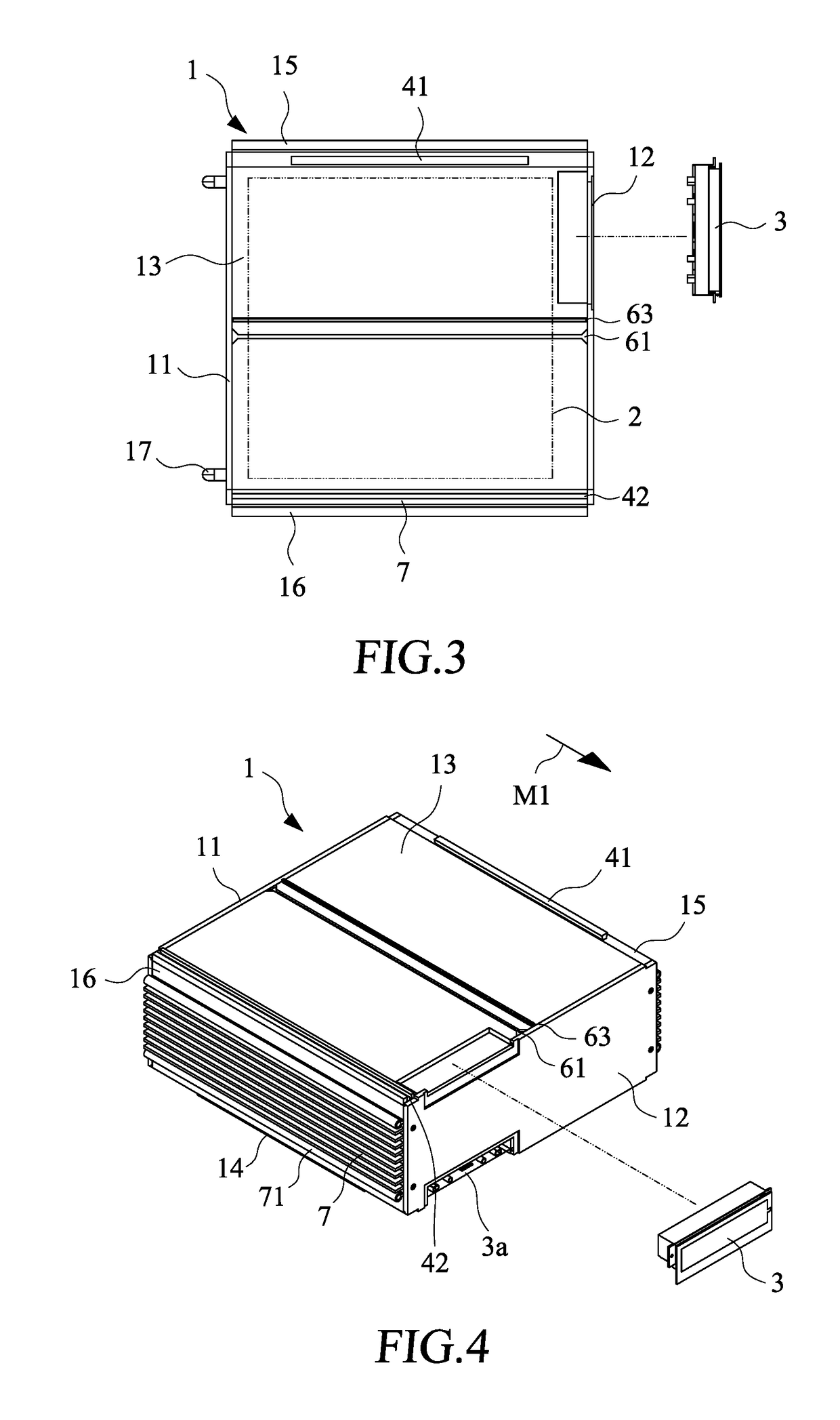
[0021]Referring to FIGS. 1-4, FIG. 1 is a perspective view, taken from a front side, showing an embodiment of the present invention; FIG. 2 is an exploded view of FIG. 1, taken from the front side, with parts being detached; FIG. 3 is a top plan view of FIG. 2; and FIG. 4 is an exploded view of the present invention, taken from the front side, with parts being detached.

[0022]As shown in the drawings, an electric power module 1 comprises an interior space defined among and by a front board 11, a back board 12, a top board 13, a bottom board 14, and a left side board 15 and a right side board 16 that are opposite to each other. A battery pack 2 is received and fixed in the interior space of the electric power module 1. The front board 11 of the electric power module 1 comprises two handles 17 mounted thereto to allow for easy operation by a user for sliding of the electric power module 1.

[0023]The back board 12 of the electric power module 1 is provided with a connector module 3 at a ...


PUM

PropertyMeasurementUnit
movementaaaaaaaaaa
heataaaaaaaaaa

Abstract

A connector assembly is provided for stacked electric power modules. Each of the electric power modules includes a front board, a back board, a top board, a bottom board, a left side board, a right side board, and a battery pack contained in the electric power module. The back board of the electric power module includes a connector module mounted thereto and the connector module includes at least one power connector connected to the battery pack and at least one signal connector. The at least one power connector and the at least one signal connector of the connector module are arranged to project beyond a horizontal surface of the top board.

Description

BACKGROUND OF THE INVENTION1. Field of the Invention[0001]The present invention relates to a connection structure of an electric power module, and in particular to a connector assembly for stacked electric power modules.2. The Related Arts[0002]Electric power modules have been widely used in various electric appliances for storage of electric power and supply of the stored electric power. For combination of multiple electric power modules, a conventional arrangement of electric power modules comprises a metal housing that surrounds a frame or a box structure and a battery pack is then deposited and fixed inside the frame or the box by means of locks, such as bolts, retention bars, retention tabs, and rivets, and is then connected with a connector or a connection cable. Such a conventional arrangement has several drawbacks, such as being hard to assemble, being difficult to disassemble and maintain, and high material costs for the frame.[0003]Further, when multiple electric power mod...

Claims


Application Information

Patent Timeline
Patent Type & Authority Patents(United States)
IPC IPC(8): H01M10/20H01R9/24H01R31/06H01M2/10H01M2/20H05K5/00H01M10/10H01M50/204H01M50/244H01M50/264H01M50/503
CPCH01M2/202H01M2/1016H01M2/1061H05K5/0021H01R9/2408H01R31/06H01M2/1077Y02E60/10H01M50/204H01M50/264H01M50/503H01M50/244
Inventor YANG, KUO-SHUN
Owner FORMOSA ELECTRONICS IND INC
Why Eureka
Try Eureka