Connecting endpiece of a flexible pipe with a spacing member, associated flexible pipe and method

a technology of flexible pipes and endpieces, which is applied in the direction of hose connections, mechanical devices, pipes/joints/fittings, etc., can solve the problems of affecting the service life of the endpiece, the axial traction of the pipe is very strong, and the endpiece does not give the full satisfaction, etc., to achieve the effect of elongating the length of the endpiece and efficient absorption of axial tension

Active Publication Date: 2018-10-30
TECH FRANCE SA
View PDF23 Cites 6 Cited by
  • Summary
  • Abstract
  • Description
  • Claims
  • Application Information

AI Technical Summary

Benefits of technology

[0025]An object of the invention is to obtain an endpiece of a flexible pipe having efficient absorption of axial tension, wherein the risk of a failure in fatigue, notably in the end segments of the armors is strongly decreased, without however significantly elongating the length of the endpiece.

Problems solved by technology

These pipes are subject to very strong forces in axial traction, notably when the extent of water in which is positioned the pipe is very deep.
Such an endpiece does not give entire satisfaction.
Sometimes, over time, the anchoring of the tensile armors becomes faulty by fatigue.
The failure may occur in the rear portion, at the area of detachment of the armors relatively to the diameter of the current length, this portion being further weakened during the mounting because of folding and unfolding the armors, required for setting into place the endpiece.
Such an endpiece does not give entire satisfaction.
The contact surface between each end segment and the resin is therefore reduced relatively to a more traditional structural endpiece, which reduces the fatigue strength of the endpiece, or which requires a considerable elongation of the endpiece for maintaining its absorption of axial tension.

Method used


Image

  • Connecting endpiece of a flexible pipe with a spacing member, associated flexible pipe and method
  • Connecting endpiece of a flexible pipe with a spacing member, associated flexible pipe and method
  • Connecting endpiece of a flexible pipe with a spacing member, associated flexible pipe and method

Examples


Embodiment Construction

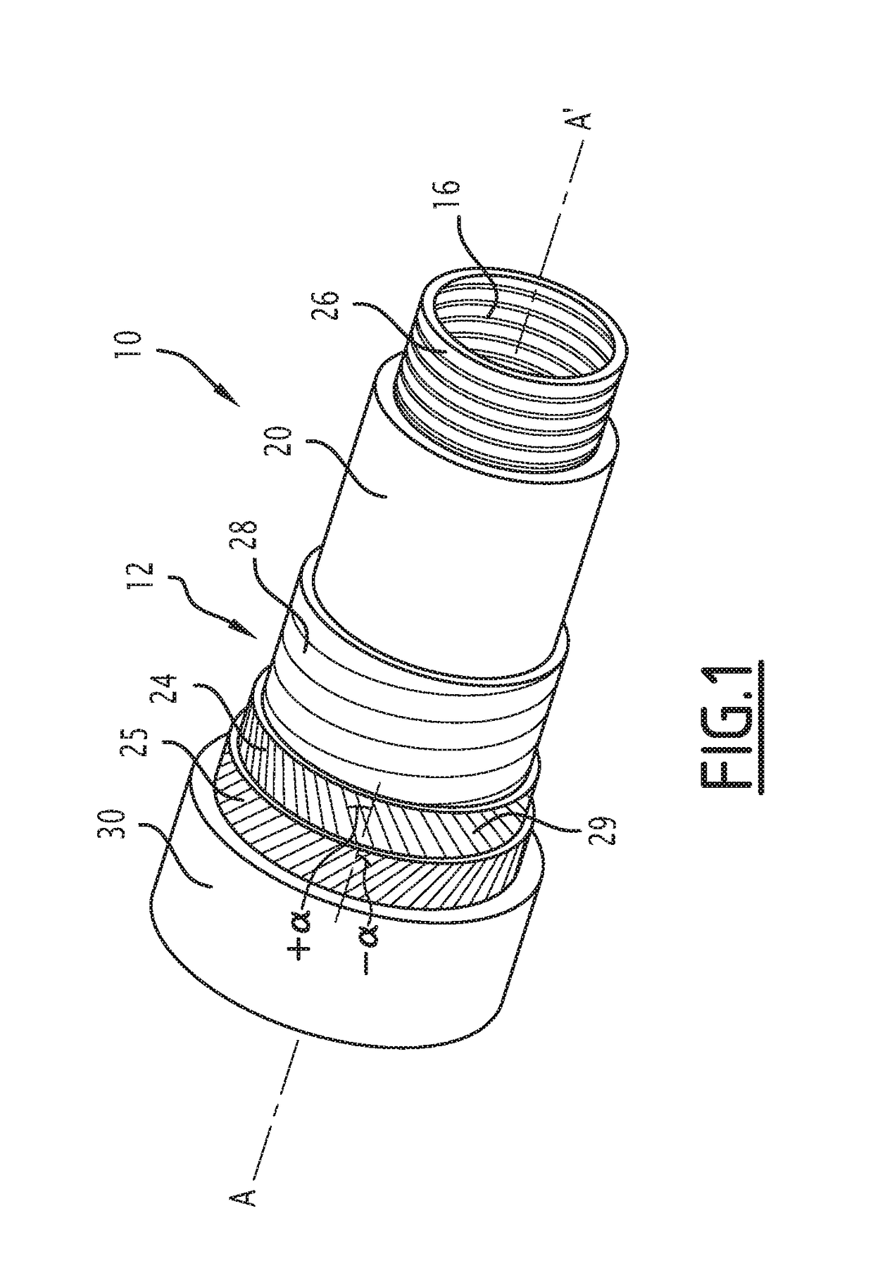
[0060]In all the following, the terms of «outer» and «inner» generally mean in a radial way with respect to the axis A-A′ of the pipe, the term «outer» meaning that it is relatively more distant radially from the axis A-A′ et the term «inner» meaning as relatively radially closer to the axis A-A′ of the pipe.

[0061]The terms of «front» and «rear» are meant axially with respect to an axis A-A′ of the pipe, the term «front» meaning as relatively more distant from the middle of the pipe and closer to one of its ends, the term «rear» meaning as relatively closer to the middle of the pipe and further distant from one of its ends. The middle of the pipe is the point of the pipe located at equal distances from both ends of the latter.

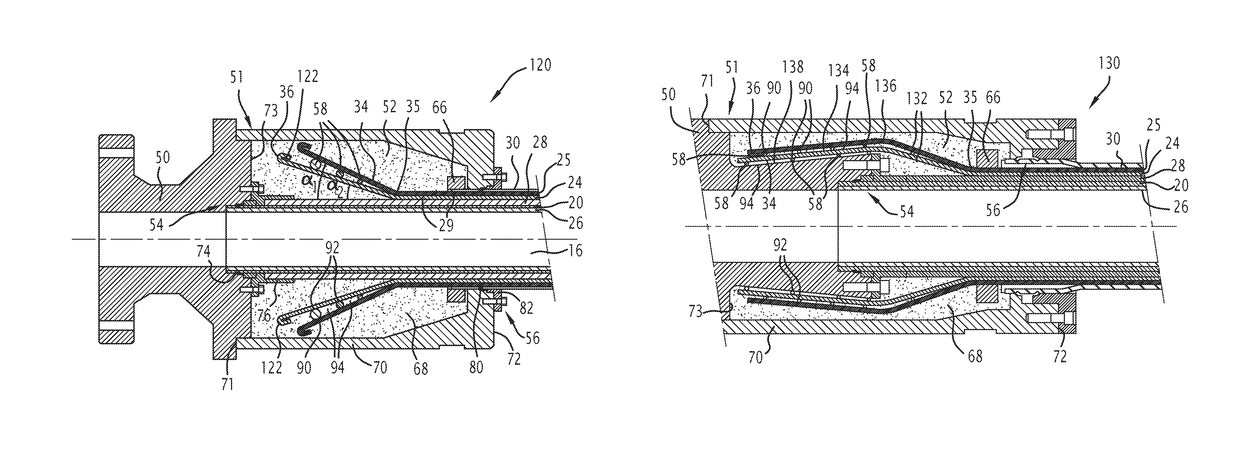
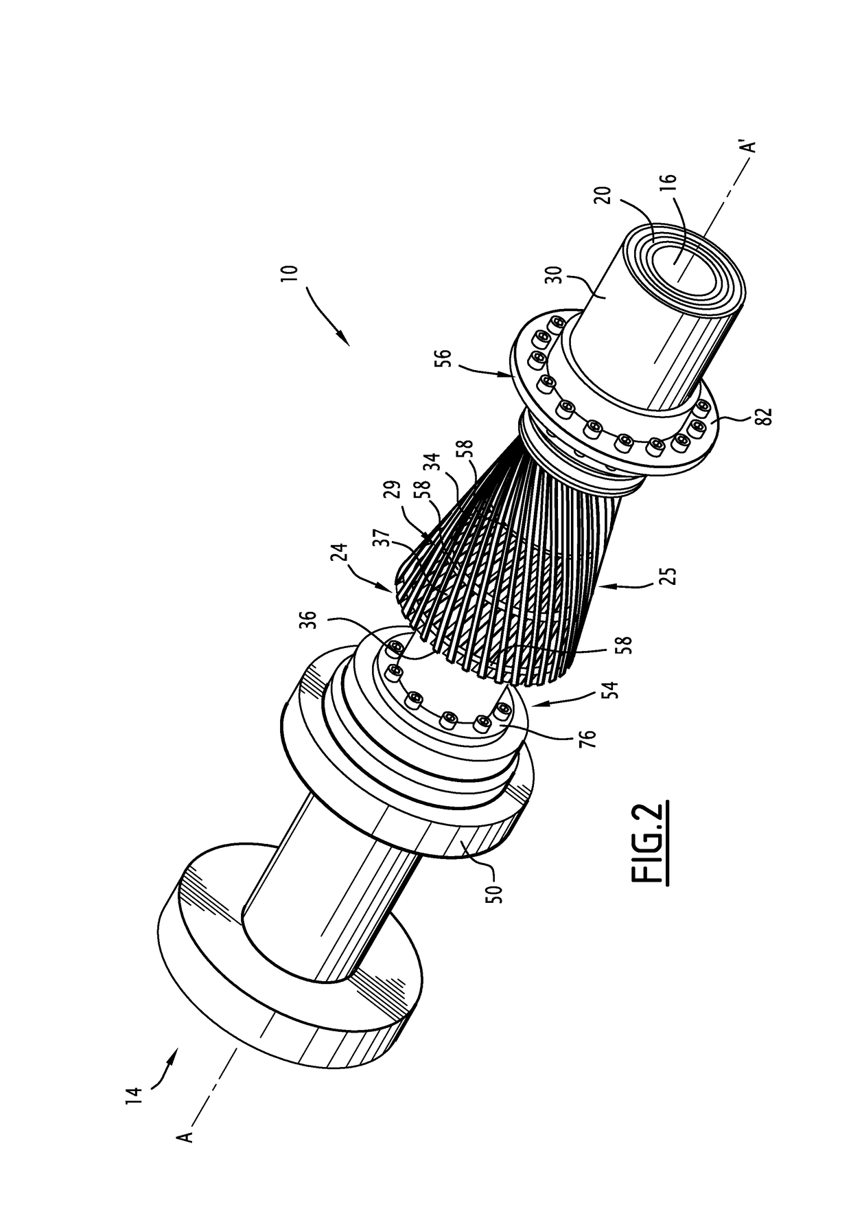
[0062]A first flexible pipe 10 according to the invention is partly illustrated by FIG. 1.

[0063]The flexible pipe 10 includes a central segment 12 partly illustrated in FIG. 1. It includes, at each of the axial ends of the central segment 12, an end endpiece 14...


PUM


Abstract

This endpiece includes at least one end segment of each armor element, an end vault and a cover, the end vault and the cover delimiting between them a chamber for receiving the end segment and a material for filling the receiving chamber, in which the end segment is embedded. The endpiece includes a spacing member positioned so as to internally bear upon the end segments of the armor elements of at least one armor layer. This spacing member defining, on at least one end segment of a armor element of said armor layer, contact areas axially spaced apart along said end segment, the contact areas delimiting between intermediate contact spaces between the filling material and the end segment.

Description

CROSS REFERENCE TO RELATED APPLICATIONS[0001]The present application is a 35 U.S.C. § 371 National Phase conversion of PCT / EP2014 / 063997, filed Jul. 1, 2014, which claims benefit of French Application No. 13 56510, filed Jul. 3, 2013, the disclosure of which is incorporated herein by reference. The PCT International Application was published in the French language.TECHNICAL FIELD OF THE INVENTION[0002]The present invention relates to a connection endpiece of a flexible pipe for conveying fluid, the flexible pipe comprising at least one tubular sheath and at least one layer of tensile armors positioned externally relatively to the tubular sheath, the layer of armors comprising a plurality of wire-shaped armor elements, the endpiece including:[0003]at least one end segment of each armor element,[0004]an end vault and a cover attached on the end vault, the end vault and the cover delimiting together a chamber for receiving the end segment,[0005]a material for filling the receiving cham...

Claims


Application Information

Patent Timeline
Patent Type & Authority Patents(United States)
IPC IPC(8): F16L31/00F16L33/01F16L33/18
CPCF16L33/18F16L33/01
Inventor BOURGET, JEAN-CHRISTOPHEBRUNO, GERMAN RAULDO, ANH TUANTOSTE, FERNANDO LEITAO GONCLANGUI, JEAN-FRANCOISREIS, FELIPECHAUDET, GUILLAUMECASTEL, YVESLE NOUVEAU, JOELBUON, ERICANDRADE DOS REIS, CARLOS RONALDO
Owner TECH FRANCE SA
Why Eureka
Try Eureka