
System and method for automated testing of user interface software for visual responsiveness

a user interface and software technology, applied in the execution of user interfaces, image enhancement, instruments, etc., can solve the problems of inability to complete the input, lose track of input provided, and confuse users into thinking the input was not completely received or accepted

Inactive Publication Date: 2018-10-30
CADENCE DESIGN SYST INC
View PDF16 Cites 16 Cited by
  • Summary
  • Abstract
  • Description
  • Claims
  • Application Information

AI Technical Summary

Benefits of technology

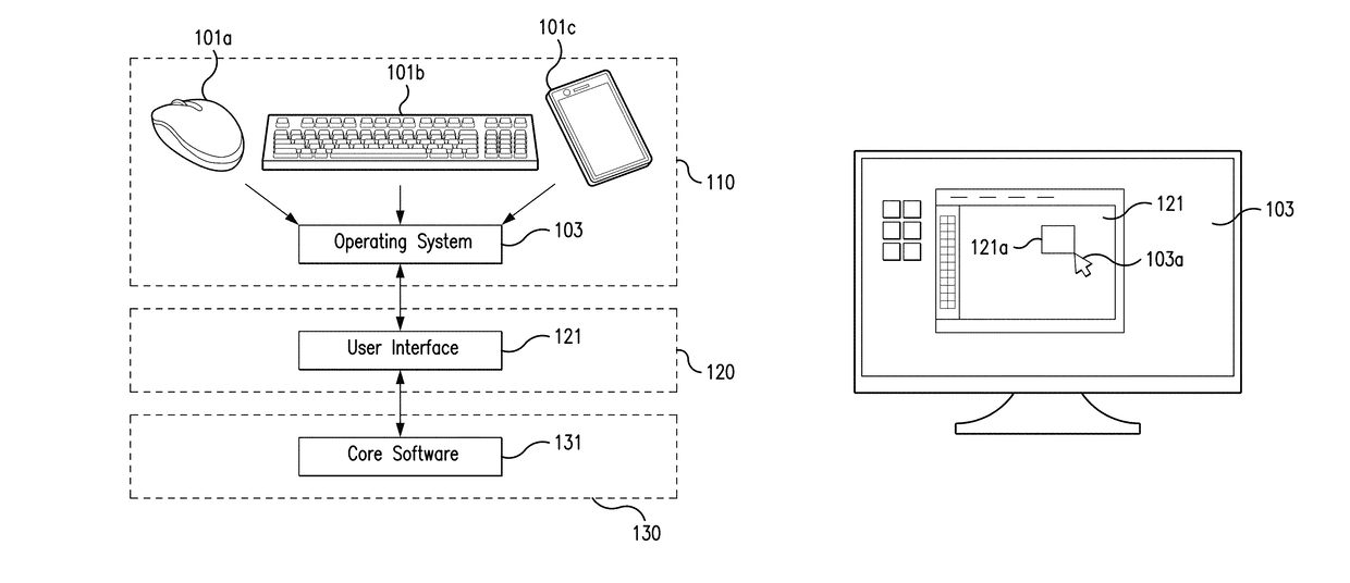
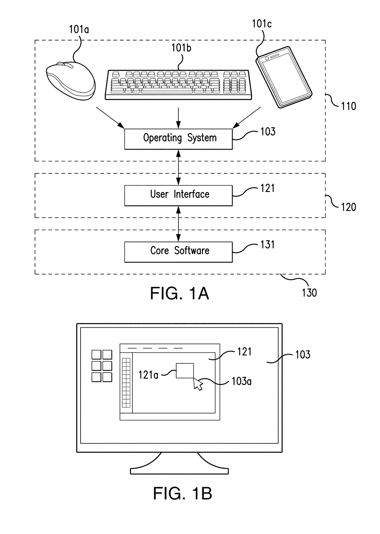
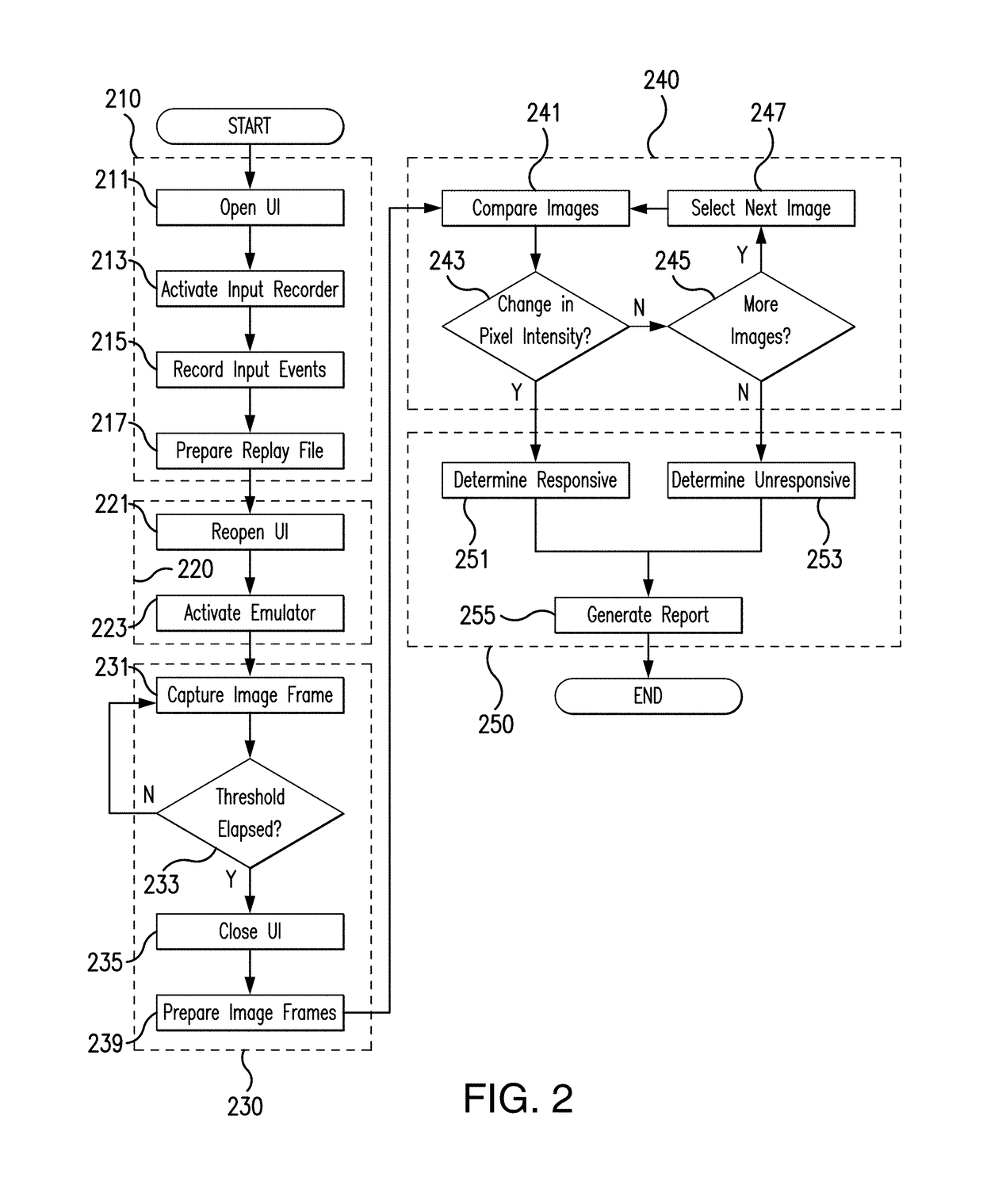
The patent describes a system and method for automatically testing user interface software for its responsiveness to user inputs. The system captures user actuation of the input device and the software's processing of this input through a root capturing unit and a canvas capturing unit, and computes a parametric difference between the two to determine the degree of visual responsiveness of the software. This allows for automated testing of user interface software for its time delay in actuating a visual prompt responsive to user manipulation of a user input device.

Problems solved by technology

Time lag in presenting an accurate visual prompt might confuse a user into thinking the input was not completely received or accepted.
The user might also, when providing rapid input, lose track of what input has been provided if the visual prompts fail to maintain speed with the input.
Ideally, this time lag should be reduced to the point where a user will not perceive it, but this cannot be done without first becoming aware of the time lag through quality assurance or other suitable testing.
Presentation of a visual prompt is dependent not only on the processing of the input with the core software, but also on the user interface itself, which may be slow to render the visual prompts due to its own software code.
Existing automated quality assurance tests for software can detect speed issues in the former but not the latter, even though the user interface may be the source of an issue.
In particular, existing automated tests have no adequate means to test whether “transitional responses” of such a prompt follow continuous input, such as location input in motion, in a clean, “smooth” manner.
Testing the speed of the user interface itself is therefore typically done in a manual fashion, which tends to be expensive, slow, and imprecise.

Method used


Image

  • System and method for automated testing of user interface software for visual responsiveness
  • System and method for automated testing of user interface software for visual responsiveness
  • System and method for automated testing of user interface software for visual responsiveness

Examples


Embodiment Construction

[0037]Reference will now be made in detail to exemplary embodiments, which are illustrated in the accompanying drawings, wherein like reference numerals refer to the like elements throughout. The embodiments are described below in order to explain the disclosed system and method by referring to the figures.

[0038]Section headings are included in this Detailed Description. It is noted that these section headings are for convenience only and should not be interpreted as limiting the scope of the claimed invention in any way.

[0039]A user interface may be slow either to generate an initial visual prompt responsive to user input, or to maintain correspondence between the visual prompt and the user input. To quantify the degree of responsiveness, to determine whether this responsiveness meets a minimum performance standard, or benchmark, and to reproduce these determinations, the input is captured, recorded, and replayed at a “root” level separate from the user interface, as one or more in...


PUM


Abstract

A benchmark test system captures and records root, or input, behavior from a user input device as one or more time-displaced samples of input. The system also separately captures and records the canvas, or visual, behavior of a user interface in response to the captured input as a series of time-displaced image frames. The image frames are analyzed for visual prompts occurring responsive to the input, and parameters of the image frames are determined. A parametric difference between corresponding ones of the root events and canvas responses is thereby computed, in order to determine a degree of visual responsiveness for the user interface software respective to the root input.

Description

BACKGROUND OF THE INVENTION[0001]The subject system and method are generally directed to the automated testing of user interface software.[0002]User interface software serves as a means of supplying input from a user to core software on the “back end,” and of supplying output from the core software to the user. An important feature of user interface software is the speed at which the interface visually responds to input, by rendering a visual prompt in the interface. Time lag in presenting an accurate visual prompt might confuse a user into thinking the input was not completely received or accepted. The user might also, when providing rapid input, lose track of what input has been provided if the visual prompts fail to maintain speed with the input. Ideally, this time lag should be reduced to the point where a user will not perceive it, but this cannot be done without first becoming aware of the time lag through quality assurance or other suitable testing.[0003]Presentation of a vis...

Claims


Application Information

Patent Timeline
IPC IPC(8): G06F3/0481G06F9/44G06F3/0484G06F11/36G06F8/38G06T7/40
CPCG06F11/3664G06F3/04842G06F3/0481G06F8/38G06T7/408G06T2207/10024G06T2200/24G06T7/90G06F9/451G06F11/3672
Inventor VARGHESE, DAVIDSAXENA, MOHITSHARMA, ANSHULGINETTI, ARNOLD JEAN-MARIE GUSTAVE
Owner CADENCE DESIGN SYST INC
Learn More