Ditch forming implement

a technology of implements and tools, applied in the direction of hand equipment, soil shifting machines/dredgers, agricultural machines, etc., can solve the problems of complex arrangement of gearboxes, high manufacturing costs, and costly repair, and achieve the effect of reducing the ratio differen

Active Publication Date: 2018-11-13
ELMERS WELDING & MFG LTD
View PDF13 Cites 0 Cited by
  • Summary
  • Abstract
  • Description
  • Claims
  • Application Information

AI Technical Summary

Benefits of technology

[0014]The use of a drive belt is simple to manufacture and maintain, while also providing some ability to absorb sudden impacts if debris such as large stones and the like being lodged in the impeller, as compared to the exclusive use of gearboxes and universal joints used to directly drive an impeller in the prior art.
[0025]In some embodiments, the implement further includes i) a first auxiliary pulley wheel rotatably supported on the frame, forwardly of the impeller member at a laterally central location, ii) a second auxiliary pulley wheel rotatably supported on the frame forwardly of the impeller member at a location laterally offset from the first auxiliary pulley wheel, iii) an auxiliary belt operatively engaged about the first and second auxiliary pulley wheels, and iv) an auxiliary shaft assembly operatively connected between the second auxiliary pulley wheel forwardly of the impeller member and the drive pulley wheel rearwardly of the impeller member, v) wherein the drive shaft assembly is connected to the first auxiliary pulley wheel so as to be arranged to transfer drive from the auxiliary drive shaft of the working vehicle to first auxiliary pulley wheel. When the impeller further includes a knife and a kicker assembly, the auxiliary shaft assembly includes a gearbox in series between the second auxiliary pulley wheel and the drive pulley wheel and wherein the gearbox includes a secondary output shaft operatively coupled to the kicker assembly to drive rotation of the kicker assembly relative to the frame. The second auxiliary pulley wheel may be larger in diameter than the first auxiliary pulley wheel to reduce the ratio difference required between the drive pulley wheel and the driven pulley wheel.

Problems solved by technology

The gearbox arrangement is typically complex and costly to manufacture, and can be subject to costly repair in the event that the implement disc becomes jammed by debris.

Method used


Image

  • Ditch forming implement
  • Ditch forming implement
  • Ditch forming implement

Examples


Embodiment Construction

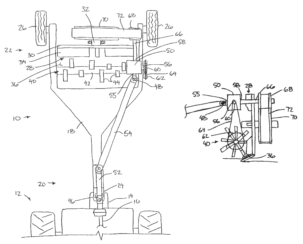
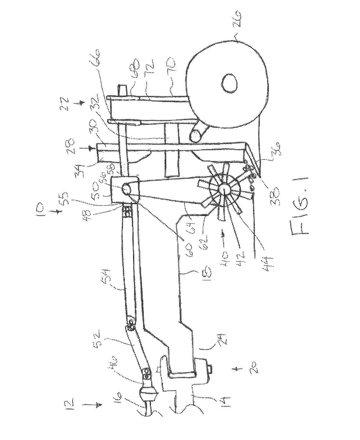
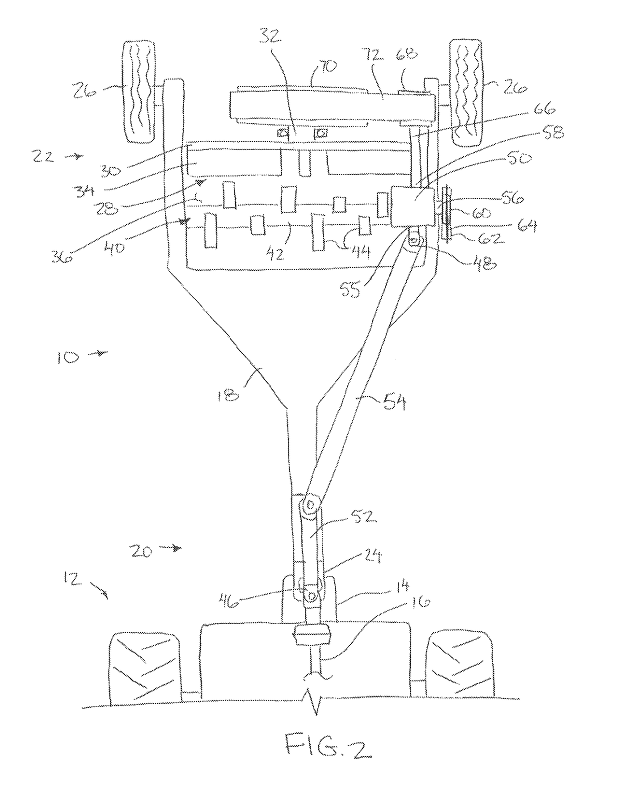
[0036]Referring to the accompanying figures there is illustrated a ditch forming implement generally indicated by reference numeral 10. The implement 10 is particularly suited for cutting a top layer of soil from the ground along a longitudinal path of the implement as the implement is advanced in a forward working direction across the ground and for spreading the cut soil laterally outward to one side relative to the forward working direction.

[0037]The ditch forming implement 10 is particularly suited for use with a working vehicle such as an agricultural tractor 12. Typically, the tractor is supported so as to be movable across the ground in a forward working direction. A hitch 14 is provided at the rear end of the tractor for connection to various types of implements to be towed. The tractor further includes a power take-off shaft 16 at the rear end thereof which is driven to rotate by the tractor under operator controls of the tractor.

[0038]The implement 10 includes a frame 18 e...


PUM


Abstract

A ditch forming implement, for use with a working vehicle, has a frame for towing connection to the working vehicle and which supports a rotatable impeller member thereon for spreading soil in a laterally outward direction relative to a forward path of the implement. A driven pulley wheel is fixed to a rear of the impeller member for rotation together relative to the frame. A drive shaft assembly operatively transfers rotational drive from a power take-off of the working vehicle to a driven pulley wheel on the frame, to be subsequently transferred to the driven pulley wheel by a drive belt connected between the driven and drive pulley wheels.

Description

[0001]This application claims the benefit under 35 U.S.C. 119(e) of U.S. provisional application Ser. No. 62 / 085,279, filed Nov. 27, 2014.FIELD OF THE INVENTION[0002]The present invention relates to a ditch forming implement which is arranged to cut a top layer of soil from the ground as the implement is displaced along the ground in a forward working direction and which is arranged to spread the cut soil transversely to the forward working direction so as to form a ditch extending in the forward working direction.BACKGROUND[0003]In many situations, it is known to be desirable to remove soil from its current location and to spread the removed soil so that it does not interfere with future operations on the land. An example is where ditches are made to drain standing water from ponds on agricultural lands.[0004]A typically ditch forming implement includes a frame arranged to be towed across the ground in a forward working direction by a tractor and which supports a impeller disc ther...

Claims


Application Information

Patent Timeline
Patent Type & Authority Patents(United States)
IPC IPC(8): E02F5/14E02F5/02A01B1/00A01D1/00A01B59/04A01B59/043
CPCE02F5/14A01B1/00A01D1/00E02F5/027A01B59/04A01B59/043
Inventor THOMPSON, MARK CHRISTOPHER
Owner ELMERS WELDING & MFG LTD
Why Eureka
Try Eureka