
Bearing cable structure while fabricating panel

a technology of bearing cable and panel, which is applied in the direction of textile cables, fastening means, rod connections, etc., can solve the problems of riveting of anti-skid rings and difficult mounting of panels on bearing cable structures, and achieve the effect of increasing service li

Active Publication Date: 2018-11-13
LIN CHU YU +1
View PDF10 Cites 0 Cited by
  • Summary
  • Abstract
  • Description
  • Claims
  • Application Information

AI Technical Summary

Benefits of technology

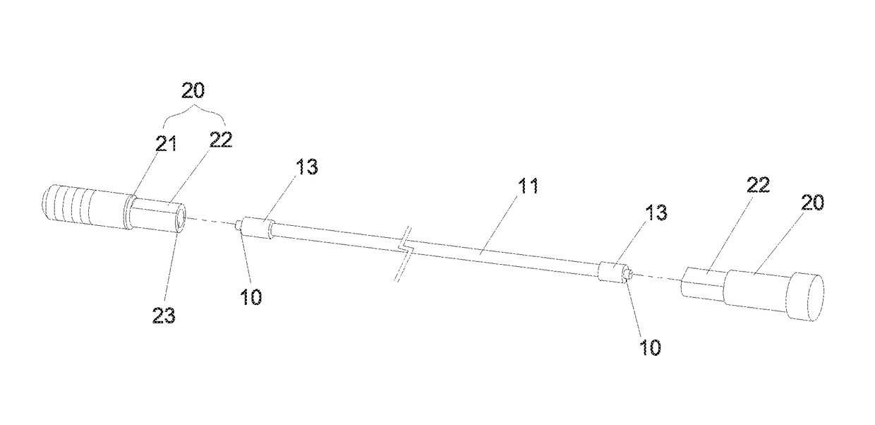
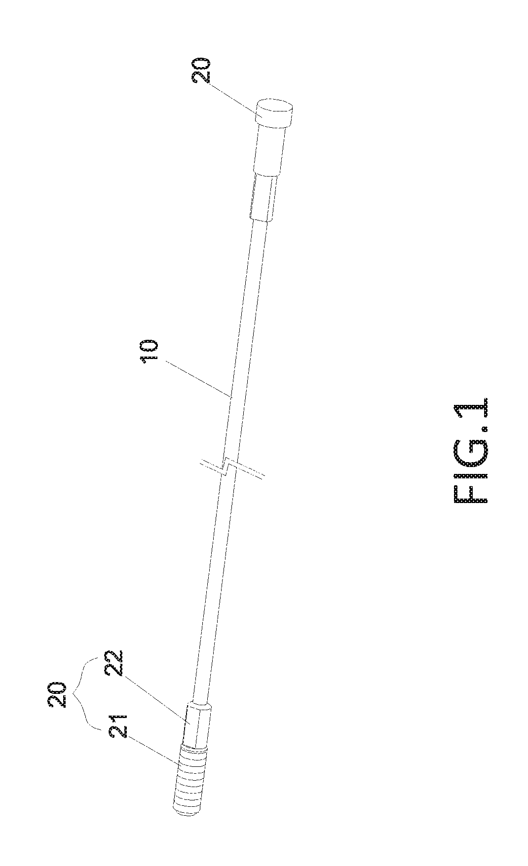
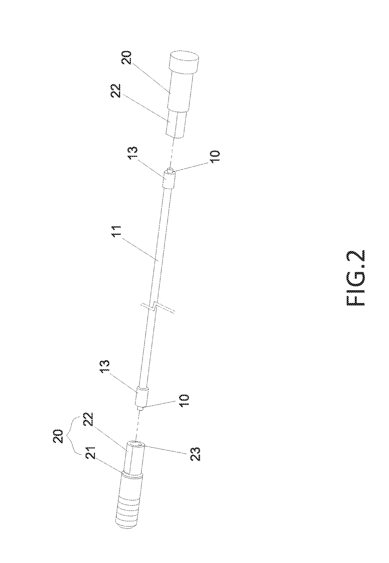
[0004]An objective of this invention is providing a bearing cable structure while fabricating panel. It may comprise a steel cable, an outer layer made by resin covers the steel cable, two connection sections are respectively formed at two ends of the steel cable which are not covered by the outer layer, an antiskid ring covers each of the two connection sections for fastening, and a diameter of the antiskid ring is larger than a diameter of the outer layer; and two sets of fixing members, a screwing section is arranged at an outer edge of each fixing member, and an axial blind hole is formed inwardly at one end of the screwing section; wherein each connection section of the steel cable is assembled to the corresponding antiskid ring and then assembled into the axial blind hole of each fixing member and further riveted to the screwing section by machine so that the fixing members are tightly connected to the outer layer of the steel cable and the steel cable and the fixing members are integrated with each other for preventing from falling off, and simultaneously the riveting of the axial blind hole of each fixing member may engage with the outer layer of the steel cable to perform double location so as to strengthen an axial pull strength of the bearing cable structure and increase service life.
[0005]The above mentioned bearing cable structure may have the advantage described as follows. The arrangement of the antiskid ring may prevent the steel cable from directly contacting with the fixing members to result in abrasion. In addition, the antiskid ring is riveted and limited by the axial blind hole and further it may strengthen the axial pull strength. Therefore, the panel which is borne on the bearing cable structure may be not easy in unstable condition, such as shifting or sliding.

Problems solved by technology

The arrangement of the antiskid ring may prevent the steel cable from directly contacting with the fixing members to result in abrasion.
In addition, the antiskid ring is riveted and limited by the axial blind hole and further it may strengthen the axial pull strength.
Therefore, the panel which is borne on the bearing cable structure may be not easy in unstable condition, such as shifting or sliding.

Method used


Image

  • Bearing cable structure while fabricating panel
  • Bearing cable structure while fabricating panel
  • Bearing cable structure while fabricating panel

Examples


Embodiment Construction

[0011]Referring now to the drawings where like characteristics and features among the various figures are denoted by like reference characters.

[0012]Please refer to FIGS. 1 to 3, the bearing cable structure while fabricating panel of this invention may comprise a steel cable 10 and two sets of fixing members 20.

[0013]An outer layer 11 made by resin covers the steel cable 10.

[0014]Two connection sections 12 are respectively formed at two ends of the steel cable 10 which are not covered by the outer layer 11. An antiskid ring 13 covers each of the two connection sections 12 for fastening. A diameter of the antiskid ring 13 is larger than a diameter of the outer layer 11. Selectively, the steel cable 10 may be composed of a plurality of steel wires which are winded around one another to form a double-axis structure or a single-axis structure.

[0015]A screwing section 22 is arranged at an outer edge of each fixing member 20 and an axial blind hole 23 is formed inwardly at one end of the ...


PUM


Abstract

A bearing cable structure while fabricating panel comprises a steel cable and two sets of fixing members. Each connection section of the steel cable is assembled to the corresponding antiskid ring and then assembled into the axial blind hole of each fixing member and further riveted to the screwing section of each fixing member by machine so that the fixing members are tightly connected to the outer layer of the steel cable and the steel cable and the fixing members are integrated with each other for preventing from falling off, and simultaneously the riveting of the axial blind hole may engage with the outer layer to perform double location so as to strengthen an axial pull strength of the bearing cable structure and increase service life.

Description

FIELD OF THE INVENTION[0001]The present invention relates to a bearing cable structure while fabricating panel, and more particularly to a bearing cable structure capable of transversely pulling the panel while fabricating to make its structure better and strengthen the axial pull strength so as to prevent from shifting or sliding.BACKGROUND OF THE INVENTION[0002]The conventional panel supporting structure may refer to Taiwanese Patent No. 1251573. It disclosed a substrate support member for conveying a linear substrate storage rack. A rectangular frame is formed by a pair of pillars and plural coupling beams which are spaced apart and arranged therebetween in a longitudinal direction of the rectangular frame. And an oblong frame is formed by plural coupling beams adjacent to the rectangular frame in a depth direction of the rectangular frame. In addition, in the rectangular frame between the pair of uprights to be spaced apart linear plural substrate support member disposed in the ...

Claims


Application Information

Patent Timeline
Patent Type & Authority Patents(United States)
IPC IPC(8): F16B7/18F16B19/04
CPCF16B19/04F16B7/18F16G11/025D07B1/18E21D21/008
Inventor LIN, CHU-YULIN, YEN-CHEN
Owner LIN CHU YU
Learn More