Piston ring

Active Publication Date: 2018-11-13
FEDERAL MOGUL BURSCHEID
View PDF11 Cites 5 Cited by
  • Summary
  • Abstract
  • Description
  • Claims
  • Application Information

AI Technical Summary

Benefits of technology

[0005]The object of the present invention therefore consists of providing a piston ring which compensates the effect of the groove tilting in a piston with conventional grooves with a rectangular cross-section. This is able t

Problems solved by technology

The result of this is that the pivot point of the piston ring running surface moves upward and thereby changes the hydrodynamic characteristics, accompanied by changed bearing-/wear behaviour toward the upper running edge, increased oil film thick

Method used


Image

  • Piston ring
  • Piston ring
  • Piston ring

Examples


Example

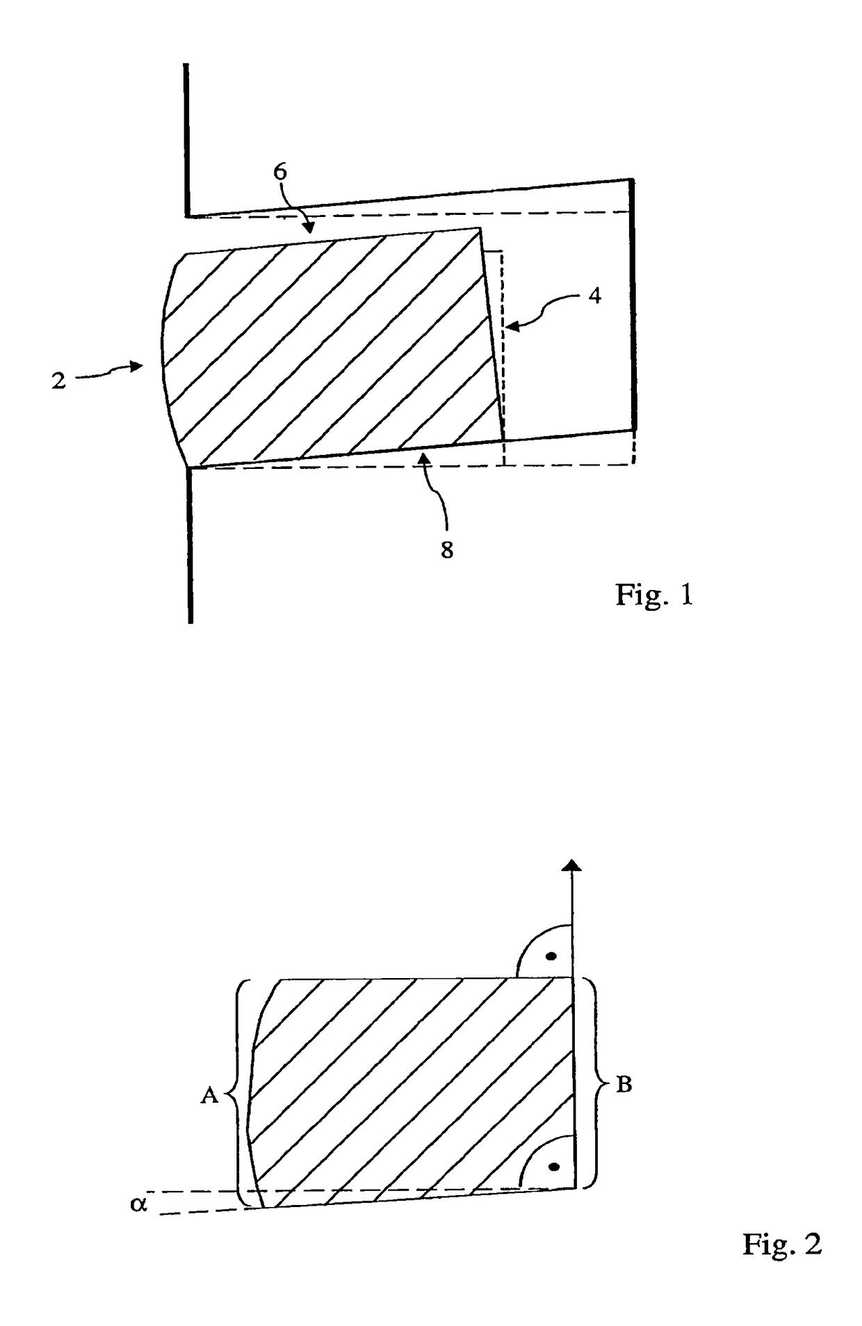
[0035]In FIG. 1 a conventional piston ring with rectangular flanks running in a parallel manner is shown. The situation with a non-tilted piston ring groove is illustrated in dashed lines. In cold state of the engine concerned, the geometry of the piston ring groove is rectangular. Through the different thermal stresses in axial direction during operation of the engine (high thermal stress at the piston crown, diminishing thermal stress in the direction of the cylinder block) different thermally caused deformations occur. Thereby, the ring groove tilts in the manner shown by solid lies (not necessarily true to scale).

[0036]In the operation of the engine, through the gas pressures occurring on the combustion, gas enters past the upper flank 6 of the piston ring into the space between ring groove and piston ring. Thereby, the piston ring is pressed downward and outward in the desired manner, in order to seal against the cylinder wall or respectively bush. The conventional piston ring ...


PUM


Abstract

A piston ring for a piston of a piston engine has an external circumferential surface (2), and internal circumferential surface (4), and upper flank (6) pointing in the direction of the piston upper side, and a lower flank (8) pointing in the direction of the piston underside. The lower flank (8) runs obliquely with respect to the upper flank (6), so that axial height (A) of the piston ring is grater at the external circumferential surface (2) than the axial height (B) at the internal circumferential surface (4), and wherein on each side of the thrust of the piston ring at least one recess (10) is provided in the upper flank (6).

Description

BACKGROUND1. Technical Field[0001]The present invention relates to a piston ring with improved bearing-, wear- and oil scraping behaviour. The invention relates in particular to a piston ring which is adapted to compensate the piston groove tilting which occurs during operation of a piston engine.2. Related Art[0002]The piston of an internal combustion engine deforms during operation under the influence of the combustion heat and the temperature distribution resulting therefrom in axial direction differently. The highest temperatures prevail at the combustion chamber side, whilst the temperature decreases in the direction of the crankcase. The consequence of this is a tilting of the piston ring grooves, so that the flanks of the piston ring groove have a downward gradient in relation to the cylinder axis.[0003]The piston ring situated in the piston ring groove lies with its lower flank under the influence of the combustion pressure with its entire surface against the lower flank of ...

Claims


Application Information

Patent Timeline
IPC IPC(8): F16J9/20
CPCF16J9/20
Inventor MITTLER, RICHARDPROEPPER, JOERN
Owner FEDERAL MOGUL BURSCHEID
Why Eureka
Try Eureka