Gasket

a gasket and seal technology, applied in the field of gaskets, can solve problems such as deteriorating seal performance, and achieve the effects of improving seal performance, high hardness, and reducing the hardness of the whole gask

Active Publication Date: 2018-11-13
ISHIKAWA GASKET CO LTD
View PDF11 Cites 2 Cited by
  • Summary
  • Abstract
  • Description
  • Claims
  • Application Information

AI Technical Summary

Benefits of technology

[0010]According to the gasket and the method for manufacturing the gasket of the present invention, at least one sheet of metal plate forming the gasket is formed by a martensitic stainless steel plate, and the high hardness portion having the hardness higher than that of the surroundings is formed at one portion of the seal bead formed in the stainless steel plate thereof. Thereby, the hardness of the whole gasket can be reduced, so that even in a case wherein a fastening force by the fastening device is low, an insufficient fastening force can be prevented, and the hardness at a portion where a seal performance is necessary is increased by the high hardness portion so as to improve the seal performance.
[0011]For example, when the gasket is fastened by the fastening device, the high hardness portion is formed at a portion which becomes a low surface pressure of the seal bead so as to reinforce the portion thereof, or the hardness rising or falling portions are provided in a circumferential direction of the seal bead so as to equalize the seal performance.

Problems solved by technology

Thus, in a case wherein the bolt fastening force is reduced, in the gasket described in Japanese Patent Application Publication No. 2000-027999, even a portion where the reinforcement of the seal performance is unnecessary becomes the high hardness as well, so that when the cylinder head and the cylinder block are fastened, the gasket causes the insufficient fastening force so as to deteriorate the seal performance.

Method used


Image

  • Gasket
  • Gasket
  • Gasket

Examples


Embodiment Construction

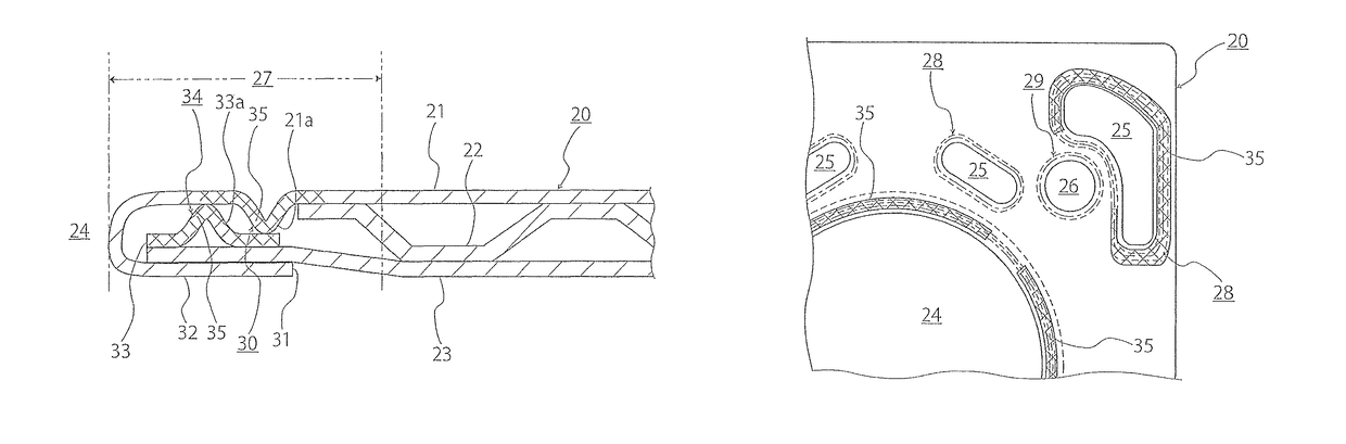
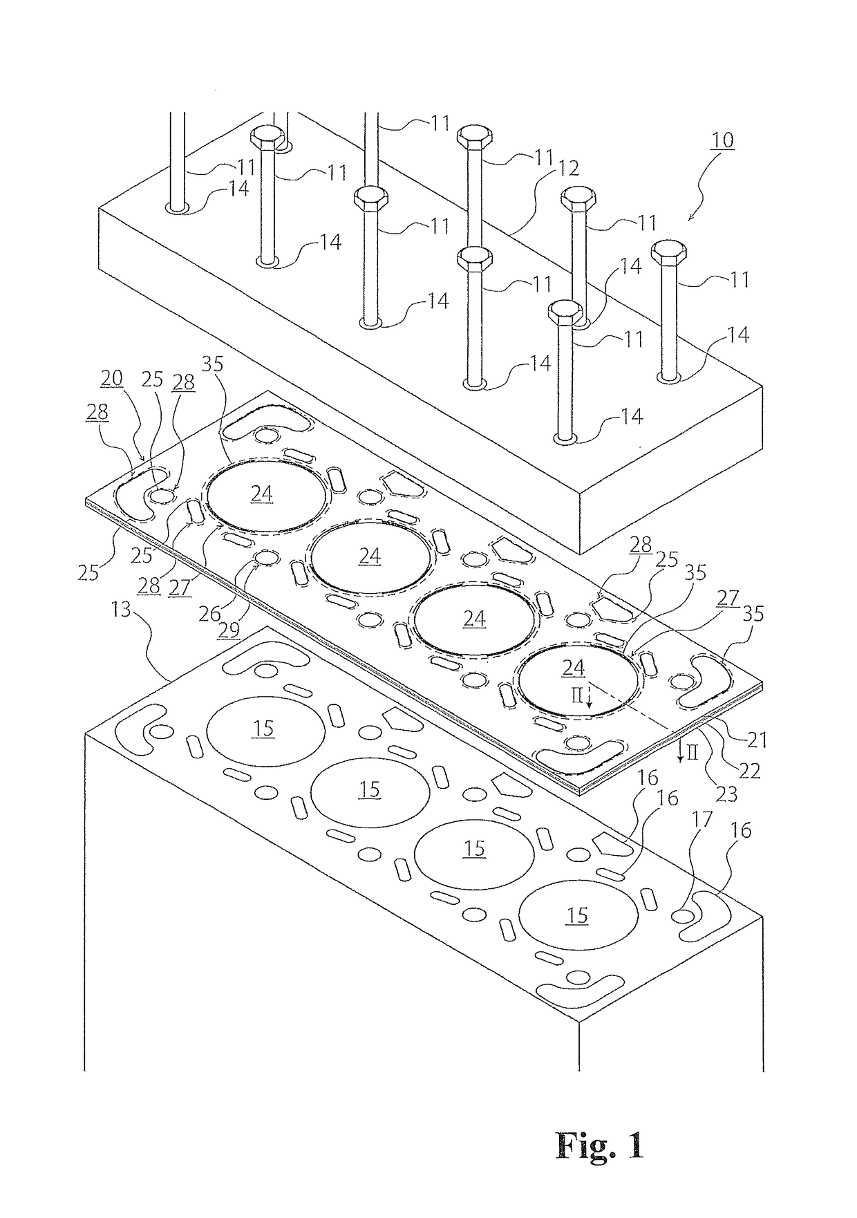
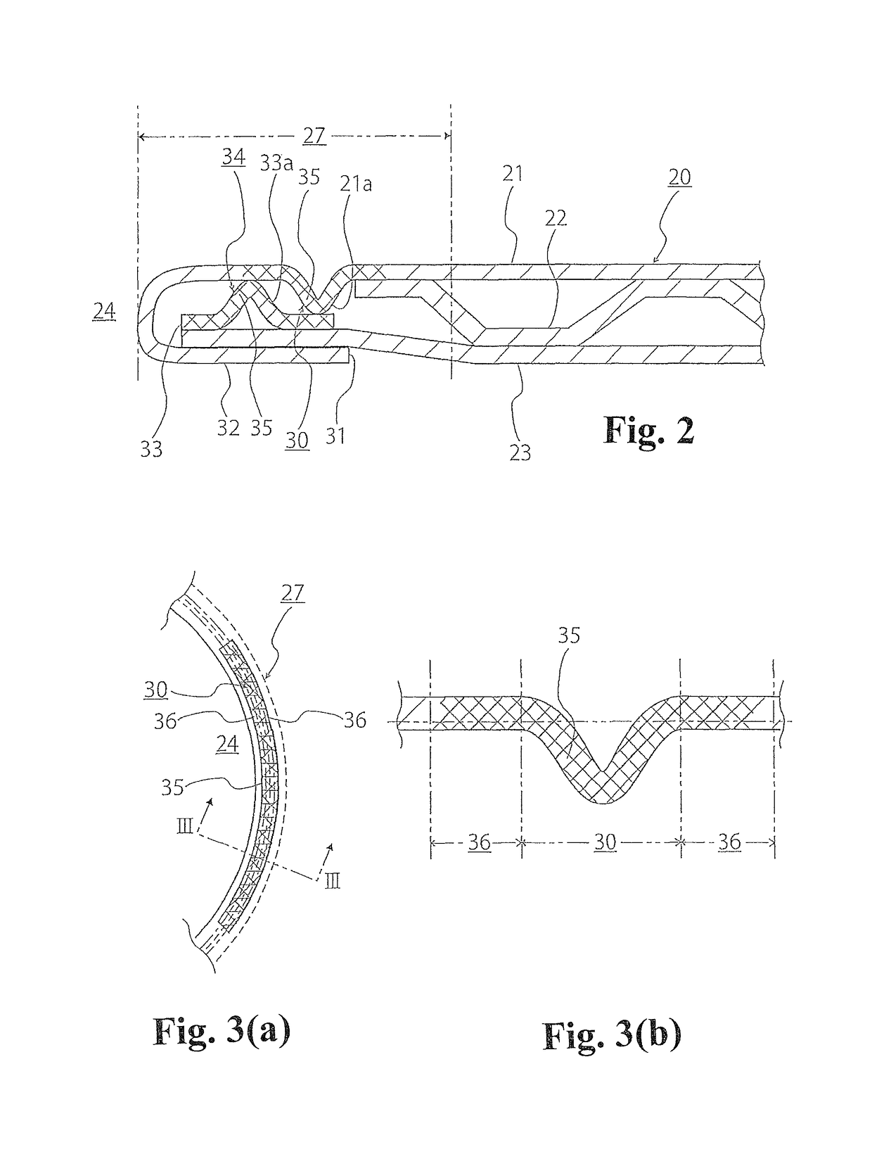
[0020]Hereinafter, embodiments of a gasket and a method for manufacturing a gasket according to the present invention will be explained. Incidentally, in FIG. 1 to FIG. 8(b), sizes are changed to easily intelligibly understand a structure, and the sizes of a cylinder bore or water and oil holes, and sizes of thickness, shape, and the like of a bead do not necessarily correspond to ratios of portions actually manufactured. Also, dotted lines in the drawings show mountain folds in a plan view, and dot-and-dash lines show valley folds.

[0021]FIG. 1 shows a structure of a gasket 20 according to an embodiment of the present invention. The gasket 20 is clamped between a cylinder head 12 and a cylinder block 13 fastened by bolts 11 which are fastening devices for an engine 10.

[0022]In the cylinder head 12, there is assembled an injector or an intake-exhaust valve which is not shown in the drawings, and insertion holes 14 pass through in an up-and-down direction. In the cylinder block 13, th...


PUM

PropertyMeasurementUnit
Vickers hardnessaaaaaaaaaa

Abstract

A gasket includes at least one metal plate to be clamped between two members fastened by fastening devices, an opening portion corresponding to a sealing hole provided in the at least one metal member, a seal bead protruding outwardly from a flat surface of the at least one metal plate, and annularly surrounding the opening portion, and insertion holes through which the fastening devices pass. At least one metal plate is formed by a martensitic stainless steel plate, and a high hardness portion having a hardness higher than that of the stainless steel plate is formed in at least one portion of the seal bead formed in the stainless steel plate.

Description

BACKGROUND OF THE INVENTION AND RELATED ART STATEMENT[0001]The present invention relates to a gasket, and more specifically, relates to the gasket which can improve a seal performance without causing an insufficient fastening force even in a case wherein a fastening force by a fastening device is low.[0002]There is proposed a gasket wherein a hardness lowering area where the hardness is locally reduced is provided only at one portion of a seal bead annularly formed in a ferritic stainless steel plate (for example, see Japanese Patent Application Publication No. 2000-027999).[0003]The gasket retains high hardness portions except for the hardness lowering area to obtain a spring characteristic, and an elongation in the hardness lowering area of the seal bead so as to prevent an edge portion of the seal bead from cracking. Incidentally, a metal plate forming the gasket is an austenitic stainless steel plate represented by SUS301-CSPH and SUS304-CSPH or the ferritic stainless steel plat...

Claims


Application Information

Patent Timeline
Patent Type & Authority Patents(United States)
IPC IPC(8): C21D1/18F16J15/08C21D8/02C21D1/34C21D9/00F02F11/00
CPCF16J15/0818C21D1/18C21D1/34C21D8/0205C21D8/0247F16J15/0806F16J15/0825C21D9/0068F16J2015/0868F02F11/002F16J2015/0837F16J15/002F16J15/102F16J2015/0856
Inventor YASUDA, KISHOYOKOYAMA, TAKANOBU
Owner ISHIKAWA GASKET CO LTD
Why Eureka
Try Eureka