Interlocking nail

a nail and interlocking technology, applied in the field of interlocking nails, can solve the problems of no improvement in fracture biology, no prior art discusses the improvement and enhanced healing of the bone, and no improvement in the bone structure of the nail, so as to maintain the strength of the nail bone construct and enhance bone healing

Inactive Publication Date: 2018-11-20
TANDIYA NITESH KUMAR
View PDF9 Cites 0 Cited by
  • Summary
  • Abstract
  • Description
  • Claims
  • Application Information

AI Technical Summary

Benefits of technology

[0010]The invention relates to an interlocking nail for fixation of transverse and short spiral fractures of, long bone particularly shaft of femur, tibia and humerus, having slot for holding plurio-potent mesenchymal stem cells derived from auto-graft particularly canacellous bone graft. The interlocking nail has 4 or 5 holes for putting interlocking bolts from lateral to medial direction or from medial to lateral direction or in anterio-posterior direction, depending on orientation of interlocking hole. Constant compression at the fracture site is achieved (irrespective of weight bearing cycle) by tightening of the Endo Compression Screw at the proximal end of the interlocking nail resulting in the stimulation of mesenchymal stem cells due to compression as well as reduction in gap at fracture site, thus enhances bone healing and union manifolds.
[0012]Another object of the invention is to provide a slot in the interlocking nail for holding mesenchymal stem cells graft, preferably from cancellous bone graft which helps in the enhanced healing and fixation of fracture. The said graft is obtained from medullary cavity of bone which is being operated. This particular slot should match with fracture site.
[0018]A further object of the invention is to achieve a static compression with tightening of the Endo Compression Screw, at fracture site irrespective of weight bearing cycle resulting in enhanced bone healing due to stimulation of stem cells, particularly plurio-potent mesenchymal stem cells that divide into the osteoblast to form new bone.

Problems solved by technology

However no improvement in fracture biology is seen.
Further, the prior art does not discuss about extra compression at the fracture provided by interlocking nail.
However, none of the prior art discusses about the improved and enhanced healing of the bone irrespective of the weight bearing cycle.
Additionally, none of the prior arts suggest the use of auto graft (i.e cancellous bone graft) in the interlocking nail obtained from medullary cavity of bone which is being operated.

Method used


Image

  • Interlocking nail
  • Interlocking nail
  • Interlocking nail

Examples


Embodiment Construction

[0041]The detailed description of the appended drawings is intended as a description of the currently preferred embodiments of the present invention, and it is not intended to represent the only form in which the present invention may be practiced. This is to be understood that the same or equivalent functions may be accomplished by different embodiments that are intended to be encompassed within the spirit and scope of the present invention.

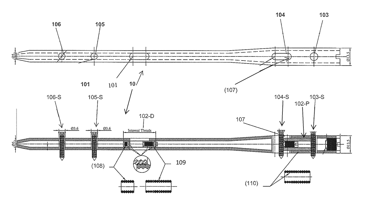
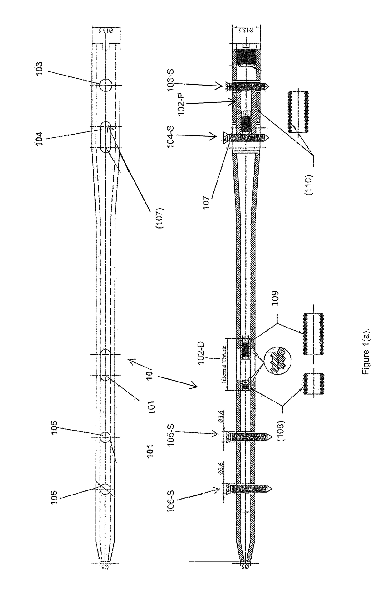
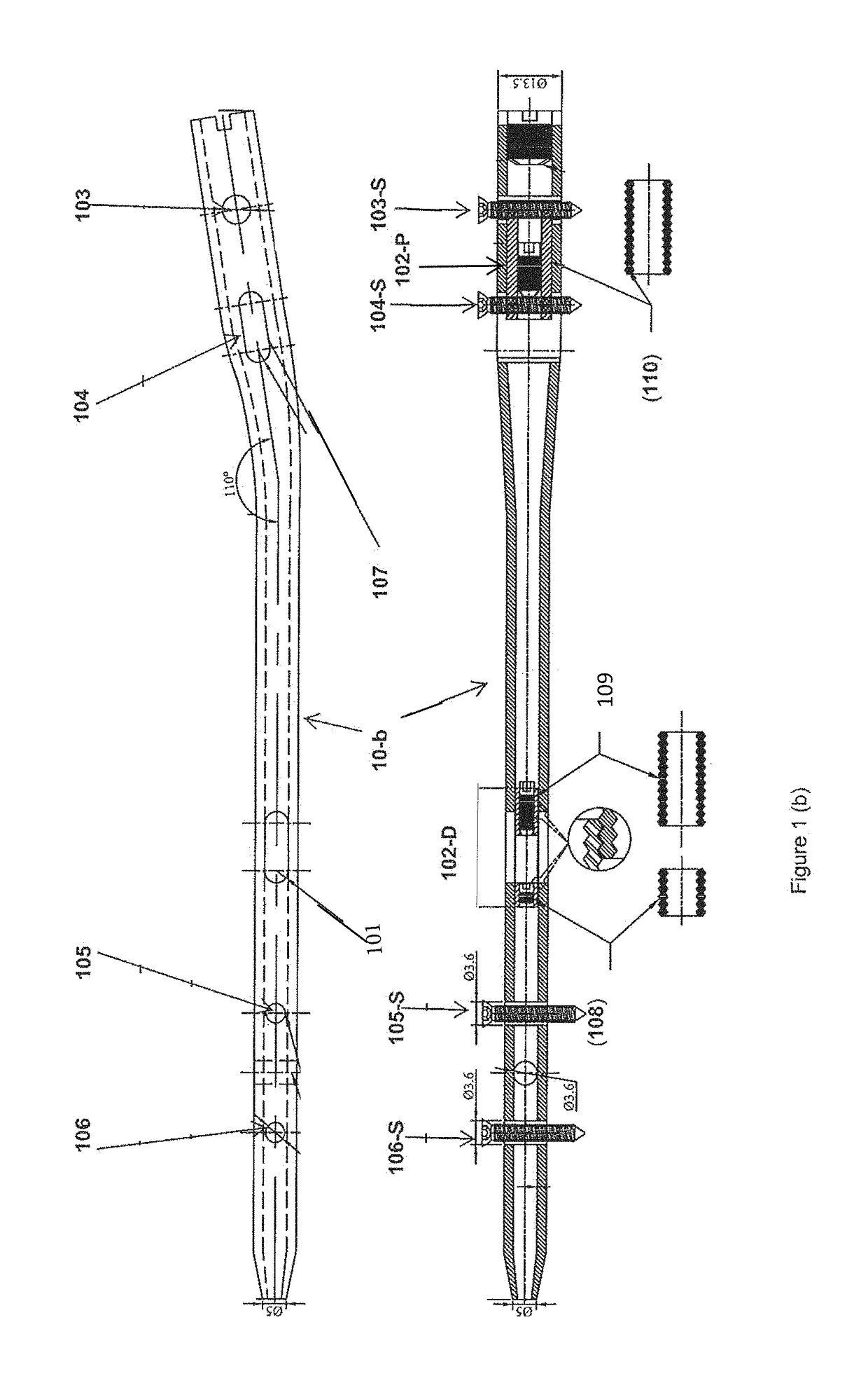
[0042]The present invention relates to an interlocking nail (10) for fixation of transverse and short spiral fractures of long bone particularly shaft of the femur, tibia and humerus. The disclosed interlocking nail specification could also be used for fractures of the radius and ulna.

[0043]The purpose of the present invention is as follows:[0044]To provide a mechanism resulting in the increase of compression forces at fracture site;[0045]To re-use the bone cells lost during reaming;[0046]To improve the bone biology locally at fracture site;[004...


PUM


Abstract

The invention relates to an interlocking nail (10) for fixation of transverse and short spiral fractures of, long bone, particularly shaft of the femur, tibia and humerus, having Graft extrusion space / slot (101) for holding stem cells graft and 4 or 5 holes for putting interlocking bolts from lateral to medial direction. Constant compression achieved (irrespective of weight bearing cycle) at the fracture site by tightening of the Endo-Compression Screws (108, 109 and 110) results in stimulation of stem cells and reduction in bone gap, thus enhances bone healing and union manifolds.

Description

[0001]This application claims priority benefit of Indian Patent Application No. 2601 / MUM / 2014 filed on Aug. 12, 2014.FIELD OF INVENTION[0002]This invention relates to an interlocking nail for fixation of transverse and short spiral fractures of, long bone, particularly shaft of the femur, tibia and humerus with the mechanism provided in the invention to augment the bone healing and union manifolds. The disclosed interlocking nail specification could also be used for fractures of the radius and ulna.BACKGROUND OF ART[0003]The intramedullary fixation devices had been in existence since 1940. The Interlocking Nail is a cylindrical hollow rod connected with the sets of 2 or 3 screws on either ends. Since then, few minor modifications such as increase in the number of screws were introduced in the design / structure of the interlocking nail.[0004]The interlocking screw provides the rotational stability at the fracture site and improves the Nail-Bone Construct stability. However no improvem...

Claims


Application Information

Patent Timeline
Patent Type & Authority Patents(United States)
IPC IPC(8): A61B17/72B25C1/00
CPCA61B17/7241A61B17/72A61B17/7225A61B17/7283B25C1/00A61B17/7233A61B2017/561
Inventor TANDIYA, NITESH KUMAR
Owner TANDIYA NITESH KUMAR
Why Eureka
Try Eureka