Multi-walled placeholder

a multi-walled, placeholder technology, applied in the field of placeholders, can solve the problems of difficult manufacturing of integrated latticework structures, difficult manufacturing of lever arrangements, and inability to uniformly distribute load across screw connections, etc., to achieve convenient in-growth and on-growth, and large surface area

Active Publication Date: 2018-11-20
BIEDERMANN TECH GMBH & CO KG
View PDF86 Cites 3 Cited by
  • Summary
  • Abstract
  • Description
  • Claims
  • Application Information

AI Technical Summary

Benefits of technology

[0051]In another embodiment, the present invention provides a modular, individually usable system for placeholders, e.g., through the use of individual components, which can be used alone, preassembled or selectively assembled. The corresponding placeholder has an extremely large surface area due to its many walls and construction from several tubular bodies, and thus markedly facilitates in-growth and on-growth. Additionally, despite the very large surface area, manufacturability is improved and, in particular, coatability and surface treatability are improved. This also results in improved in-growth properties. In particular, the modular assembly allows for individual surface treatment of the single components. Thus, different coating of the individual components may take place, i.e., of the various cylindrical-tubular bodies located in the different positions. This results in an implant having good mechanical stability and improved in-growth characteristics, which is especially suitable for vertebral discs or placeholders. An optimum fusion element for orthopedics is thus achieved.

Problems solved by technology

However, such integral latticework structures are difficult to manufacture and have to be adjusted and manufactured individually to suit every application case.
Although this device facilitates very precise length adjustment, the lever arrangement is complicated to manufacture.
However, this arrangement does not uniformly distribute the load across the screw connections and does not effectively allow in-growth by the surrounding tissue because of the close arrangement of the sleeve bodies.
However, the corrugated form of the one implant part again makes for complicated manufacture.

Method used


Image

  • Multi-walled placeholder
  • Multi-walled placeholder
  • Multi-walled placeholder

Examples


Embodiment Construction

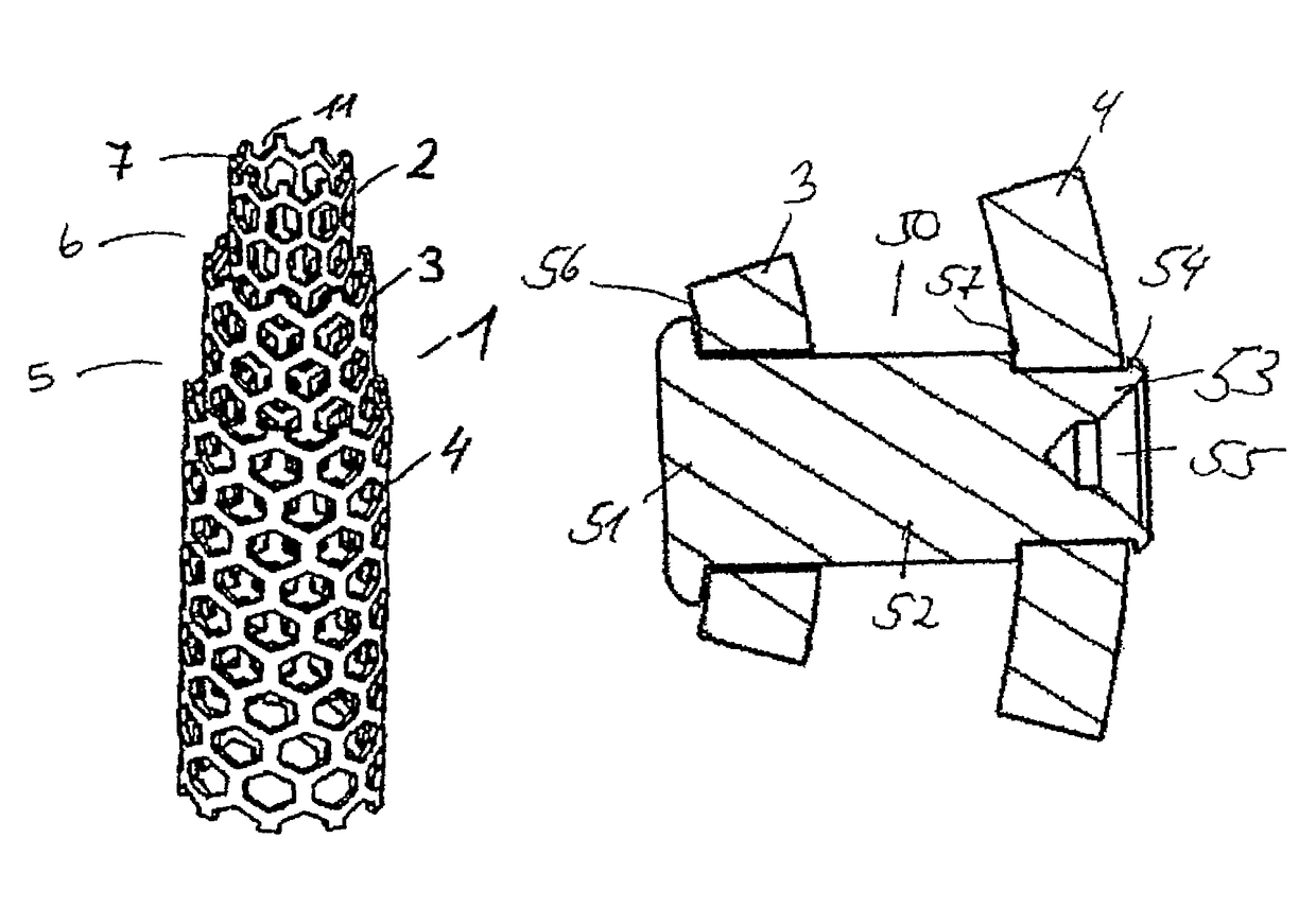
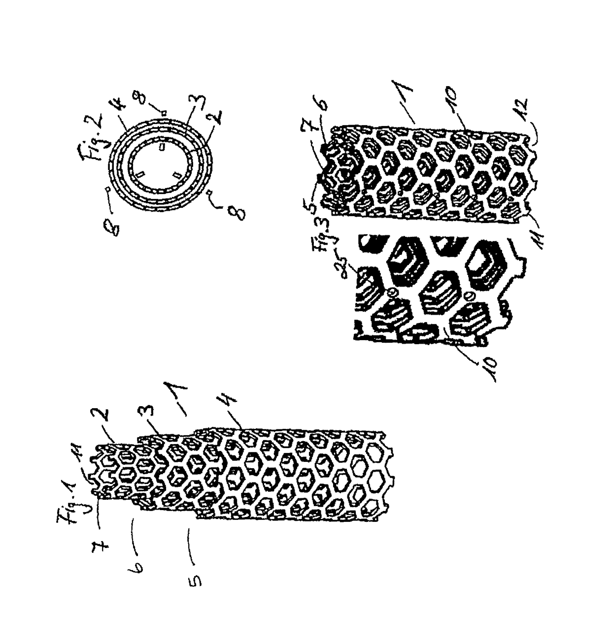
[0089]FIG. 1 shows a perspective representation of a first embodiment of a placeholder 1 of the invention in which the tubular bodies 2, 3 and 4 are partially arranged inside each other.

[0090]The tubular body 4, which has the largest diameter, accommodates the tubular bodies 2 and 3 of smaller diameter. Tubular body 3, which has the next largest diameter, accommodates the tubular body 2 of the smallest diameter.

[0091]The tubular body 3 is arranged in the tubular body 4, such that it projects over the edge 5 of the tubular body 4 in the direction of the longitudinal axis of the placeholder 1. Similarly, the tubular body 2 is arranged in the tubular body 3, such that it projects over the edge 6 of the tubular body 3.

[0092]The tubular bodies 2, 3 and 4 are connected to each other via pins 8 (see FIG. 2), which are detachably inserted by press fit through cut-outs or holes 25 (see FIG. 3) of the tubular bodies 2, 3, 4. Accordingly, it is possible, when the pins 8 have been removed, to a...


PUM

PropertyMeasurementUnit
angleaaaaaaaaaa
angleaaaaaaaaaa
perimeteraaaaaaaaaa

Abstract

A placeholder for vertebrae or vertebral discs includes a tubular body, which along its jacket surface has a plurality of breakthroughs or openings for over-growth with adjacent tissue. The placeholder includes at least a second tubular body provided with a plurality of breakthroughs and openings at least partially inside the first tubular body. The first and second tubular bodies can have different cross-sectional shapes, can be are arranged inside one another by press fit or force fit or can be connected to each other via connecting pins and arranged side by side to one another in the first body.

Description

CROSS-REFERENCE TO RELATED APPLICATION(S)[0001]This application is a continuation of U.S. patent application Ser. No. 15 / 012,827, filed Feb. 1, 2016, which is a continuation of U.S. patent application Ser. No. 13 / 914,471, filed Jun. 10, 2013, now U.S. Pat. No. 9,254,199, which is a continuation of U.S. patent application Ser. No. 11 / 645,228, filed Dec. 22, 2006, now abandoned, which claims the benefit of and priority from U.S. Provisional Patent Application Ser. No. 60 / 753,854, filed Dec. 23, 2005, and the benefit of and priority from U.S. Provisional Patent Application Ser. No. 60 / 808,028, filed May 23, 2006, the disclosures of all of which are incorporated herein by reference.BACKGROUND[0002]The present invention refers to a placeholder for implantation into a human or animal body, especially as a placeholder for vertebrae or vertebral discs, a method for manufacturing such a placeholder, and a modular system for such a placeholder.[0003]Placeholders, especially for vertebrae or v...

Claims


Application Information

Patent Timeline
Patent Type & Authority Patents(United States)
IPC IPC(8): A61F2/44G02F1/1345G02F1/1343H01L27/12A61B17/70H01L29/49A61B17/80A61B17/72H01L29/45A61F2/28A61F2/30
CPCA61F2/44A61F2/442A61F2/4465G02F1/13439G02F1/13458A61F2002/30146A61F2002/30148A61F2002/30153A61F2002/30154A61F2002/30156A61F2002/30235A61F2002/30441A61F2002/30451A61F2002/30485A61F2002/30492A61F2002/30507A61F2002/30551A61F2002/30601A61F2002/30672A61F2002/30787A61F2002/30841A61F2002/30912A61F2002/4475A61F2220/0025A61F2220/0041A61F2220/0058A61F2230/0006A61F2230/0008A61F2230/0013A61F2230/0015A61F2230/0017A61F2230/0019A61F2230/0021A61F2230/0023A61F2230/0069A61F2310/00023A61F2310/00796H01L27/12H01L27/124H01L29/458H01L29/4908A61B17/7001A61B17/72A61B17/80A61F2/30767A61F2/4455A61F2002/2825A61F2002/3024A61F2002/3055A61F2002/3097A61F2002/30115A61F2002/30126A61F2002/30131A61F2002/30133A61F2002/30144A61F2002/30143A61F2002/30433A61F2002/30593A61F2/46A61F2/02A61F2/00
Inventor BIEDERMANN, LUTZMATTHIS, WILFRIEDRAPP, HELMAR
Owner BIEDERMANN TECH GMBH & CO KG
Why Eureka
Try Eureka