Transcutaneous electrostimulator and methods for electric stimulation

a transcutaneous electrostimulator and electric stimulation technology, applied in the field of electric stimulation devices, can solve the problems of poor fit, inability of soldiers to have the will or concentration to continue to discharge their duties, and attempts to retain user couplers, etc., to achieve adequate pain control, reduce constant, and reduce symptoms

Active Publication Date: 2018-11-20
NERVANA LLC
View PDF284 Cites 24 Cited by
  • Summary
  • Abstract
  • Description
  • Claims
  • Application Information

AI Technical Summary

Benefits of technology

[0028]There are additional advantages to transcutaneous measures that can consistently, reliably, and universally deliver electrical signals for neuromodulation. One benefit provided by such transcutaneous measures includes instances where surgical implantation is impractical and / or could not be predicted as a future need, such as pain mitigation for an injured soldier, for example. In this circumstance, it is advantageous to be able to effectively connect electrodes to a soldier who is on the battlefield with ease, reliability, and resistance to environmental conditions, especially motion, and have the electrical signal be well-tolerated by the subject and be consistently effective. Furthermore, the known positive effects that VNS has on mood elevation and enhanced concentration are effects that may be beneficial in situations that are not otherwise anticipated or require only intermittent therapy rather than the long-term therapy, such as provided by an implantable device. An example of this benefit could be understood in the military, in general, because keeping mood, morale, and concentration up is either more or less difficult depending on the situation. For example, if a sniper just lost a fellow soldier or friend to an improvised explosive device, it may be difficult for that soldier to have the will or concentration to continue to discharge his / her duties as effectively as before. Having a device available that can be interfaced quickly to that soldier, which not only will enhance his / her mood but increase concentration when the need arises to take an accurate shot at the enemy, is clearly advantageous. Other soldiers may have fluctuations in mood or concentration that can mitigated on an “as needed” basis with a transcutaneous device.
[0044]In other exemplary embodiments, the software, circuit, or “chip” that determines device functionality (i.e., number of signal types, power, amplitude, frequency and pulse duration, selectability between user couplers) can be removably replaced with routines or chips having other functionality or can be reprogrammable at the factory, or through the use of an app where the device having the app communicates with the present systems or the device and can be integrated into the device itself. In an exemplary chip configuration, the chip can be removed and replaced into a specific socket or slot, or can be integrated into a sealed or partially sealed battery pack that contains the chip, where the act of simply removing an existing battery pack and replacing it with a new one having the same or different chip can instantaneously change or maintain device functionality. This configuration reduces manufacturing costs as well as reduces consumer costs as it is no longer necessary to produce distinctly different generator units with different functionality or require the consumer to replace the entire device to alter its functionality if that is desirable or indicated. The chip also can allow the same device to have expanded applications.

Problems solved by technology

For example, if a sniper just lost a fellow soldier or friend to an improvised explosive device, it may be difficult for that soldier to have the will or concentration to continue to discharge his / her duties as effectively as before.
Each of the prior art attempts to retain a user coupler have failed either because it was designed to fit only one particular anatomical location and the progression of the technology made such a design obsolete or the retention device was just too uncomfortable for daily use or was designed for specific anatomic geometries that are quite variable causing poor fit, poor retention, and poor contact in a large portion of the population.

Method used


Image

  • Transcutaneous electrostimulator and methods for electric stimulation
  • Transcutaneous electrostimulator and methods for electric stimulation
  • Transcutaneous electrostimulator and methods for electric stimulation

Examples


Embodiment Construction

[0242]As required, detailed embodiments of the present invention are disclosed herein; however, it is to be understood that the disclosed embodiments are merely exemplary of the invention, which can be embodied in various forms. Therefore, specific structural and functional details disclosed herein are not to be interpreted as limiting, but merely as a basis for the claims and as a representative basis for teaching one skilled in the art to variously employ the present invention in virtually any appropriately detailed structure. Further, the terms and phrases used herein are not intended to be limiting; but rather, to provide an understandable description of the invention. While the specification concludes with claims defining the features of the invention that are regarded as novel, it is believed that the invention will be better understood from a consideration of the following description in conjunction with the drawing figures, in which like reference numerals are carried forwar...


PUM


Abstract

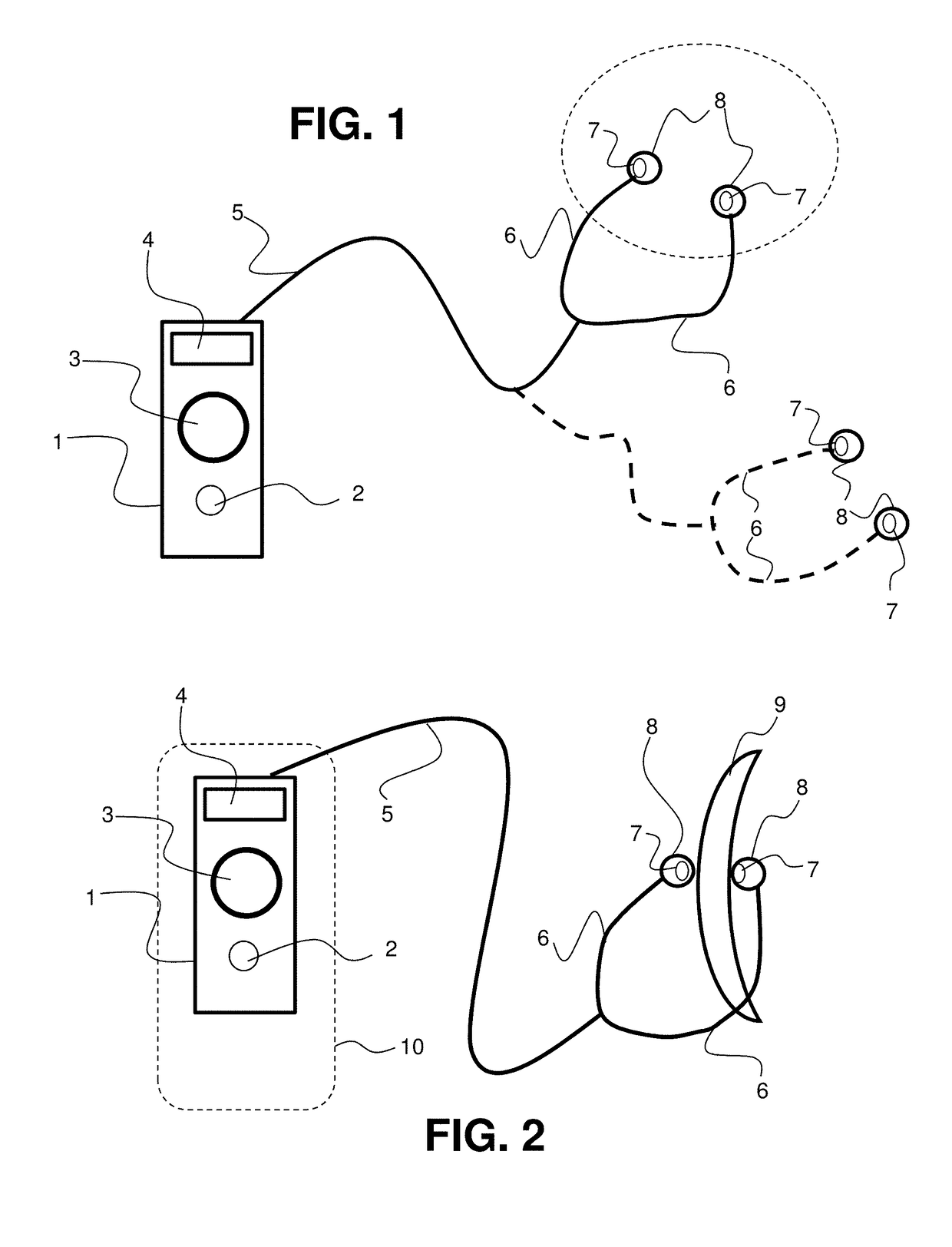
An electrostimulation device includes a computer generating an electrostimulation generator control signal and outputting a music signal, a transcutaneous electrostimulation generator, an electronic signal conduit, and an electrode coupler. The generator receives the generator control signal and the music signal, generates a nerve electrostimulation signal dependent upon the generator control signal, and outputs the nerve electrostimulation signal at the stimulation output and the music signal at an audio output. The coupler fits in an ear canal, has a speaker connected to the audio output to output the music signal into the ear canal when worn, and has electrostimulation electrodes conductively connected to the stimulation output through the electronic signal conduit to receive the nerve electrostimulation signal and positioned to contact tissue within the canal to transcutaneously apply the nerve electrostimulation signal thereto. The coupler supplies the nerve electrostimulation signal while music outputs from the speaker.

Description

CROSS-REFERENCE TO RELATED APPLICATIONS[0001]The present application:[0002]claims the priority, under 35 U.S.C. § 119, of U.S. Provisional Patent Application No. 62 / 274,595, filed Jan. 4, 2016;[0003]is a continuation-in-part of copending U.S. patent application Ser. No. 14 / 738,156, filed Jun. 12, 2015, which application claims priority to U.S. Provisional Patent Application Nos. 62 / 121,759, filed Feb. 27, 2015, and 62 / 011,985, filed Jun. 13, 2014; and[0004]is a continuation-in-part of PCT / US2015 / 035715, filed Jun. 13, 2015, which application:[0005]claims priority to U.S. patent application Ser. No. 14 / 738,156, filed Jun. 12, 2015, which application:[0006]claims priority to U.S. Provisional Patent Application Ser. Nos. 62 / 121,759, filed Feb. 27, 2015, and 62 / 011,985, filed Jun. 13, 2014;the prior applications are herewith incorporated by reference herein in their entireties.STATEMENT REGARDING FEDERALLY SPONSORED RESEARCH OR DEVELOPMENT[0007]Not ApplicableFIELD OF THE INVENTION[0008]...

Claims


Application Information

Patent Timeline
Patent Type & Authority Patents(United States)
IPC IPC(8): A61N1/00H04R1/10A61N1/04A61N1/36A61N1/05
CPCA61N1/36014A61N1/0456A61N1/0472A61N1/36036H04R1/1016H04R1/1008A61N1/0476A61N1/0526A61N1/36021A61M21/02H04R1/10A61M2021/0027A61N1/3603A61N1/36034A61M21/00A61N1/00A61N1/04A61N1/05A61N1/18A61N1/32A61N1/372
Inventor CARTLEDGE, RICHARDCARTLEDGE, DANIELBRANNON, AMIFALK, KERMITMAYBACK, GREGORY L.
Owner NERVANA LLC
Why Eureka
Try Eureka