Injection moulding device having a rotatable centre part

a technology centre part, which is applied in the field of injection moulding device, can solve the problems of increasing forces and other problems, and achieve the effects of flexible design, optimal guided direction, and optimized weight distribution

Active Publication Date: 2018-11-20
FOBOHA GERMANY
View PDF27 Cites 4 Cited by
  • Summary
  • Abstract
  • Description
  • Claims
  • Application Information

AI Technical Summary

Benefits of technology

[0016]The main body of the center block can be manufactured by means of a 3D-printing process. This has the advantage that the interior and in particular the media lines can be flexibly designed and optimally guided. This results in an optimized weight distribution and an improved cooling. Furthermore, the main body may have cavities which contribute to weight reduction. This is not possible in the case of conventionally manufactured main bodies. Alternatively or in addition, targeted reinforcements (not shown) can be inserted or incorporated. After hardening or tempering of the printed material, the side surfaces or the connecting surfaces can be mechanically finished as needed.

Problems solved by technology

However, at the higher processing speeds associated therewith, increased forces also occur, as the machine parts must be more strongly accelerated and decelerated so that they can keep up with the pace of the machine.

Method used


Image

  • Injection moulding device having a rotatable centre part
  • Injection moulding device having a rotatable centre part
  • Injection moulding device having a rotatable centre part

Examples


Embodiment Construction

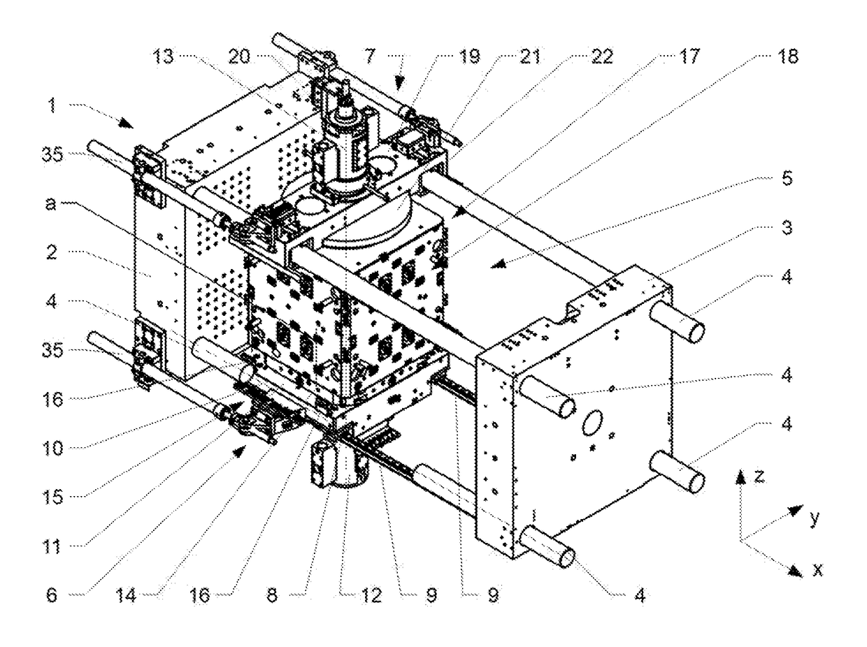
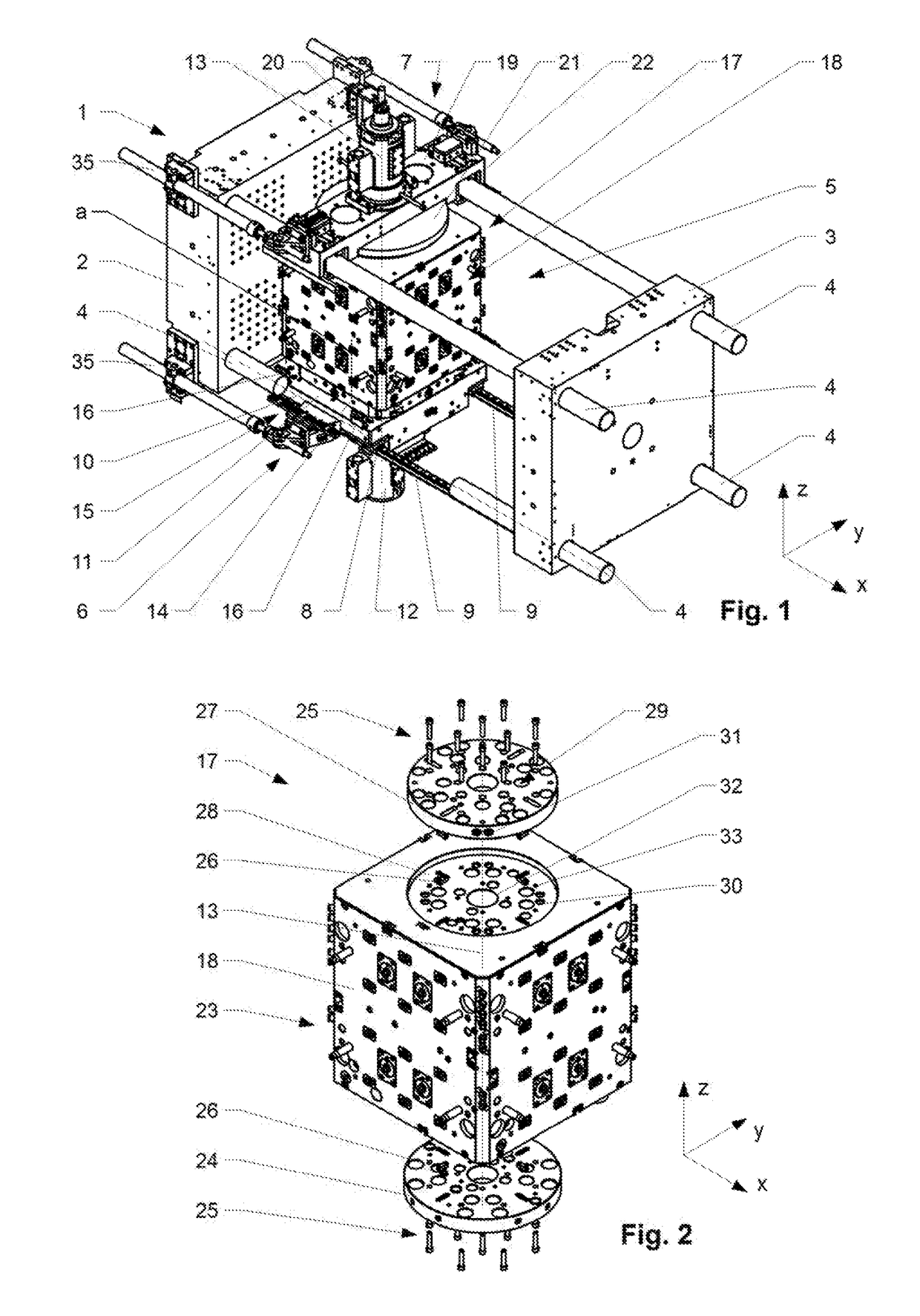
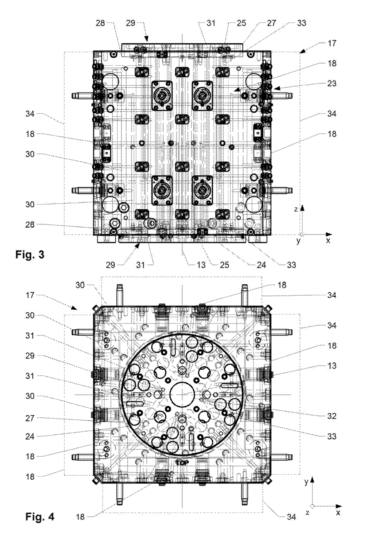
[0023]The injection molding device 1 has a first mold mounting plate 2 and a second mold mounting plate 3 movable relative thereto. The mold mounting plates 2, 3 are used for mounting the first and second mold halves of an injection mold (not shown in detail). The mold mounting plates 2, 3 are arranged movably to one another in a first direction (x-direction) along longitudinal guides, here in the form of tie bars 4 of the injection molding device 1. Depending on the area of application and manufacturer of the injection molding device, other types of longitudinal guides are possible. A holding device 5 can be recognized between the two mold mounting plates 2, 3. This has a lower holding device 6, which in the embodiment shown comprises a lower cross member 11, which is arranged movably in the direction of the tie bar 4 (x-direction). The lower cross member 11 is supported in the vertical direction on a rail system 9 on a machine bed (not shown in detail) of the injection molding dev...


PUM

PropertyMeasurementUnit
axis of rotationaaaaaaaaaa
densityaaaaaaaaaa
distanceaaaaaaaaaa

Abstract

The invention relates to a retaining device (5) for a rotatable center block (17) in an injection molding device (1), comprising a lower rotary plate (14) rotatable about an axis of rotation (13) and driven by a motor (15), the lower rotary plate being used for retaining the rotatable center block (17). The retaining device (5) comprises a lower cross member (7), which is mounted movably in the longitudinal direction (x) on guide rails (9) while supported on a machine bed of the injection molding device by means of first bearing blocks (8). The retaining device (5) can have two bearing blocks (16), by means of which the lower cross member (7) is supported in the circumferential direction relative to lower beams (4) of the injection molding device. For a further increase in efficiency, the center block (17) has a main body made of a material of lower density than a coupling plate (23) operatively connected thereto.

Description

BACKGROUND OF THE INVENTION[0001]Field of the Invention[0002]The present invention relates to the field of tools and machines for injection molding of plastic and other thermoplastic materials.[0003]Discussion of Related Art[0004]Injection molding devices having one or more rotating center parts are known from the prior art. These are used for the efficient manufacture of multi-component plastic parts by injection molding. At least one rotatable mold center part (center block), which is fixed to a holding device and is rotatably arranged about an axis of rotation, is arranged between two mold halves, the mold halves being movable against one another along tie bars in a first direction. The rotatable mold center part has at least two parallel side surfaces, along which it interacts with the two mold halves for the formation of the cavities. In certain embodiments, the rotatable mold center part can interact at least on one side with a further rotatable mold center part. Coordinating ...

Claims


Application Information

Patent Timeline
Patent Type & Authority Patents(United States)
IPC IPC(8): B29C45/04B29C45/26B29C45/16B29C45/17B29C45/32
CPCB29C45/2606B29C45/045B29C45/1628B29C45/2681B29C45/1742B29C2045/326B29C2045/1764
Inventor ARMBRUSTER, RAINER
Owner FOBOHA GERMANY
Why Eureka
Try Eureka