
Air conditioning system for hybrid vehicles

a hybrid vehicle and air conditioning technology, applied in the direction of machines/engines, transportation and packaging, engine starters, etc., can solve the problems of limiting the operation of the air conditioning system for heating the vehicle room, reducing the heating efficiency of the vehicle room, so as to achieve optimal control of the vehicle room temperature, optimally correct the opening position, and accurately compensate the injection of the vehicle room

Active Publication Date: 2018-11-20
HANON SYST
View PDF5 Cites 0 Cited by
  • Summary
  • Abstract
  • Description
  • Claims
  • Application Information

AI Technical Summary

Benefits of technology

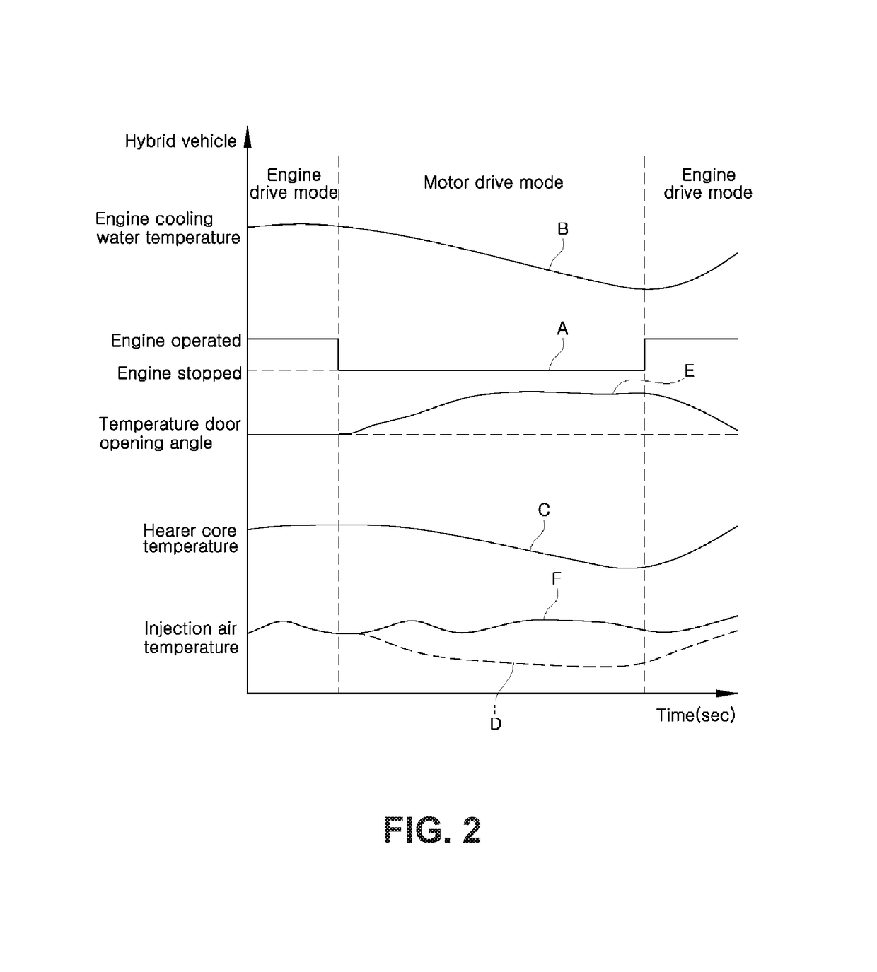
This patent describes an air conditioning system for hybrid vehicles that can adjust the position of the temperature control door based on the actual injection air temperature in the vehicle, as well as other factors that may affect the temperature. By controlling the opening angle of the temperature control door, the system can accurately compensate for changes in injection air temperature and optimize the temperature control of the vehicle. Additionally, the system takes into account factors such as engine cooling water temperature and controls the engine re-operation time point accordingly, in order to prevent unnecessary engine re-operation and improve fuel efficiency.

Problems solved by technology

However, the frequent stop of the engine of the hybrid vehicle limits the operation of an air conditioning system for heating a vehicle room.
This leads to a problem in that the vehicle room heating efficiency is sharply reduced.
This reduces the vehicle room heating efficiency and significantly impairs the ride comfort.
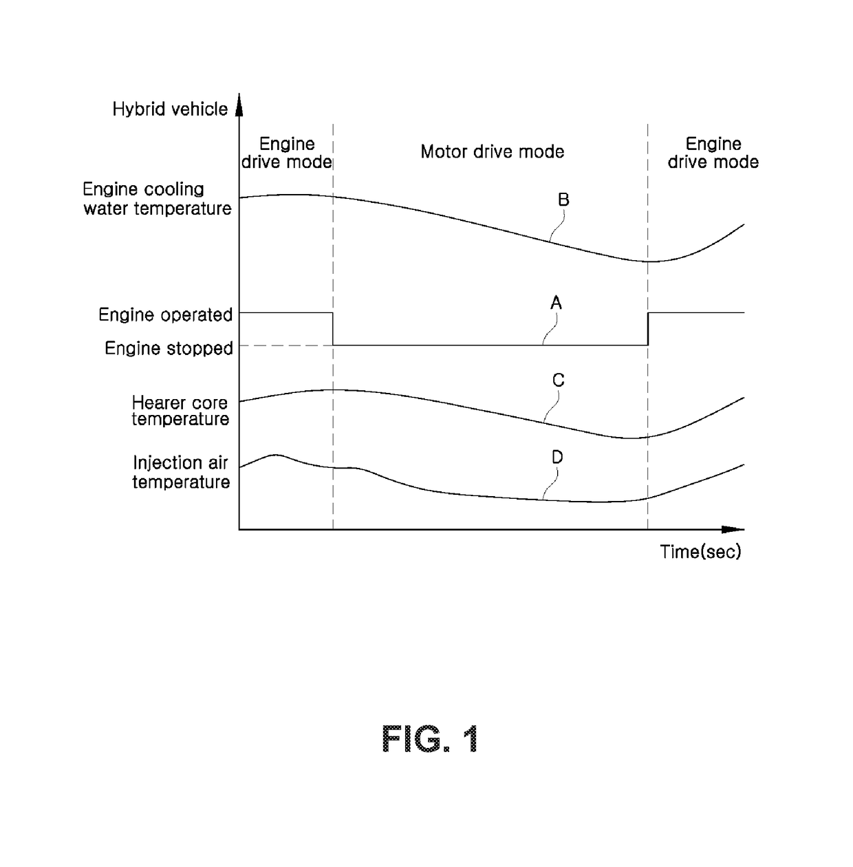
For that reason, in the motor drive mode, it is impossible to accurately control the opening angle of the temperature door in conformity with the change in the actual temperature of the air injected into the vehicle room.
This makes it impossible to accurately compensate the vehicle room injection air temperature in the motor drive mode.
Thus, in the technique of the related art in which the opening angle of the temperature door is corrected solely based on the reduction of the engine cooling water temperature, it is impossible to accurately control the opening angle of the temperature door in conformity with the change in the temperature of the air injected into the vehicle room.
This makes it impossible to accurately compensate the vehicle room injection air temperature in the motor drive mode.
Thus, the vehicle room temperature cannot be maintained at a pleasant temperature in the motor drive mode.
This leads to a problem in that the engine re-operation phenomenon occurs frequently.
For that reason, the engine may be unnecessarily re-operated even when the target air injection temperature is set low and even when the vehicle room injection air temperature can be sufficiently compensated even under an engine cooling water temperature of a lower limit value or less.
Since the engine is automatically re-operated regardless of the opening angle of the temperature door if the engine cooling water temperature is a predetermined lower limit value or less, there is a problem in that the engine may be unnecessarily re-operated even when the vehicle room injection air temperature can be sufficiently compensated by controlling the opening angle of the temperature door without having to re-operating the engine.
This poses a problem in that the engine re-operation phenomenon occurs frequently in the motor drive mode, consequently reducing the fuel efficiency.

Method used


Image

  • Air conditioning system for hybrid vehicles
  • Air conditioning system for hybrid vehicles
  • Air conditioning system for hybrid vehicles

Examples


Embodiment Construction

[0042]A preferred embodiment of an air conditioning system for hybrid vehicles according to the present invention will now be described in detail with reference to the accompanying drawings. Components similar to those of the related art described earlier will be designated by like reference symbols.

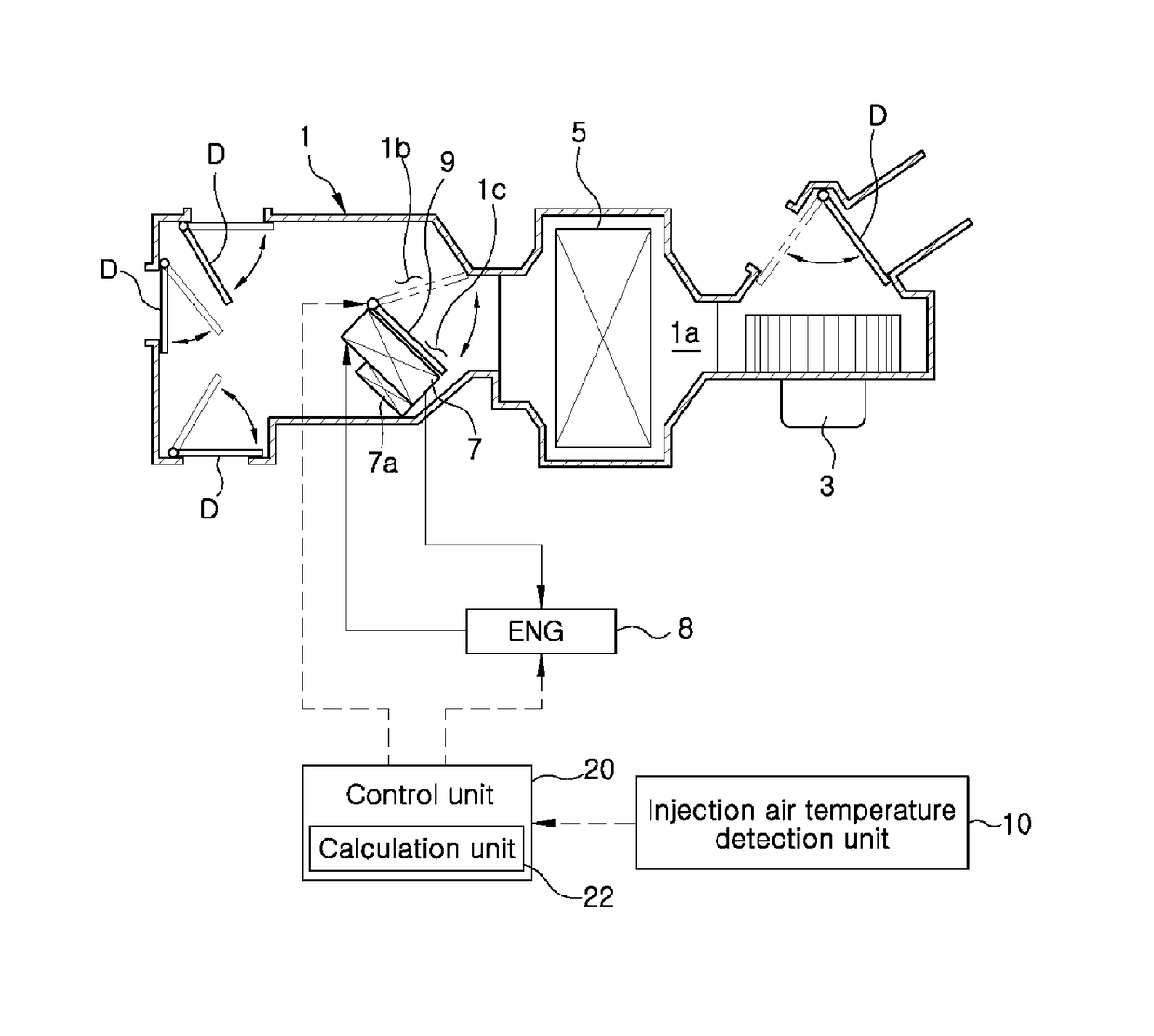
[0043]Prior to describing features of an air conditioning system for hybrid vehicles according to the present invention, an air conditioning system for motor vehicles will be briefly described with reference to FIG. 4.

[0044]The air conditioning system for motor vehicles includes an air conditioner case 1 within which a blower 3, an evaporator 5 and a heater core 7 are installed.

[0045]The blower 3 is configured to draw an internal or external air and to blow the air toward an internal path 1a of the air conditioner case 1. The evaporator 5 is configured to cool the air blown toward the internal path 1a. The heater core 7 is configured to heat the air blown toward the internal path 1a. Par...


PUM


Abstract

An air conditioning system for hybrid vehicles includes a control unit configured to re-operate an engine if an engine cooling water temperature is reduced to a lower limit value or less after entry into a motor drive mode, and configured to stop the engine if the engine cooling water temperature is increased to an upper limit value or more. The control unit is configured to change the upper limit value and the lower limit value depending on a target air injection temperature calculated according to an internal / external temperature condition and a user-set temperature so that, in the motor drive mode, a re-operation time point of the engine is actively changed according to the target air injection temperature.

Description

CROSS-REFERENCE TO RELATED APPLICATIONS[0001]This application is a United States national phase patent application based on PCT / KR2015 / 010017 filed Sep. 23, 2015, which claims the benefit of Korean Patent Application No. 10-2014-0126658 filed Sep. 23, 2014 and Korean Patent Application No. 10-2015-0134437 filed Sep. 23, 2015. The disclosures of the above patent applications are hereby incorporated herein by reference in their entirety.TECHNICAL FIELD[0002]The present invention relates to an air conditioning system for hybrid vehicles. More particularly, the present invention pertains to an air conditioning system for hybrid vehicles capable of compensating a vehicle room temperature in an optimal state by optimally correcting an opening position of a temperature door during a motor drive mode and capable of preventing an unnecessary re-operation of an engine and consequently improving fuel efficiency by re-operating the engine depending on the temperature of an engine cooling water ...

Claims


Application Information

Patent Timeline
Patent Type & Authority Patents(United States)
IPC IPC(8): B60H1/00B60H1/03B60W20/40F02N11/08B60H1/06
CPCB60H1/00885B60H1/004B60H1/00778B60H1/00878B60H1/034B60H1/06B60W20/40F02N11/084F02N11/0829F01P2037/00F01P2050/24F02N2200/023F02N2200/0804F02N2200/122Y02T10/48B60H1/00021B60H1/00735B60W10/06B60W10/30B60W20/00B60H2001/0015B60W2510/30B60W2510/0676B60W2710/30B60W2555/00B60W20/10Y02T10/40
Inventor YOO, SANG JUNBAEK, CHANG HYUN
Owner HANON SYST
Learn More