Modular vehicle assembly system and method

a vehicle assembly and module technology, applied in the direction of electrode maintenance, soldering apparatus, auxillary welding devices, etc., can solve the problems of increasing the complexity of new assembly lines, increasing the difficulty of facilities, and increasing the difficulty of building new assembly lines

Active Publication Date: 2018-11-20
COMAU LLC
View PDF190 Cites 6 Cited by
  • Summary
  • Abstract
  • Description
  • Claims
  • Application Information

AI Technical Summary

Benefits of technology

[0011]Examples of the present invention include a modular vehicle assembly line having a plurality of assembly cells having modular systems and equipment which improves on the above complexities and disadvantages in prior assembly systems and methods.
[0012]In one example of the invention, a modular application equipment (AE) support pallet device is selectively used to elevationally support and secure application equipment, for example liquid sealant storage tanks and distribution pumps, above the assembly line and assembly tools, for example robots. The modular pallet is selectively connected to the assembly cell frame directly adjacent to, or in close proximity to, the robot (or other assembly tools or equipment) using the specific application equipment and further provides a simple logistical path to convey the consumable material, sealant, fasteners etc. directly into the assembly cell and the robot for application. In an example of a method of the invention, the modular pallet device can be pre-constructed and shipped to the application equipment supplier wherein the application equipment can be mounted and tested at the supplier prior to delivery and installation at the assembly plant. Power, data and material conveying cables and hoses for the mounted peripheral equipment can simply be connected to coordinating equipment at a system integrator's facility or directly at assembly plant for a “plug and play” device enabling efficient installation, connection and commission / testing at the assembly plant.
[0013]In another example of an aspect the invention, a modular assembly tool (AT) platform or tray is provided to easily locate and secure required assembly tools and associated AE devices to the modular assembly cell infrastructure. In one example, a floor-level modular robot platform is provided. In the example, an industrial programmable robot, control cabinet and associated accessory devices are preinstalled on a modular AT platform or frame which coordinates with the existing modular assembly cell infrastructure. The modular support platform similarly allows the equipment to be pretested prior to arrival at the system integrator or assembly plant and provides quick and precise positioning with the existing modular assembly cell infrastructure. The simple, secure and precise positioning of the robot relative to the platform, and the platform relative to the assembly cell or station, provides immediate, predictable and highly repeatable location of the robot to the other assembly cell equipment greatly reducing the time and effort to positionally orient, program, and calibrate the robot over traditional devices and methods. The exemplary modular AT platform further provides secure and predictable positioning of AE devices relative to the robot, for example weld tip dressers for spot welding gun end effectors connected to the robots, further adding to plug and play advantages on installation at the assembly plant as described above.
[0018]The method provides at least the advantages of simultaneous and parallel design activities for non-model specific and model specific equipment, immediate design release of the modular non-model specific technical details of the assembly lines, increased commission of the equipment at the suppliers and rapid installation and final commission at the assembly plant through connection of the modular assembly line components and application equipment mounted thereto. This results in compressed timing to design and install an assembly facility at lower cost and overall lowered business risk which is more evenly shared between the OEM and suppliers awarded portions of the business.

Problems solved by technology

The ability to quickly change over from building one type of body to another causes significant difficulty for facilities due to the limited amount of space around assembly lines and the time required to change over equipment and components that are specific to one vehicle body.
The design, build, installation and commission (testing or prove-out) of new assembly lines is an enormously time consuming and expensive endeavor for both suppliers and the customer vehicle original equipment manufacturers (OEM's) ultimately responsible for operation of the assembly facilities and production of the vehicles.
This is further complicated by OEM's typically awarding portions of the assembly line Time A and Time B equipment to many different suppliers to leverage the respective supplier's expertise.
If a supplier falls behind in the design, build or installation of Time A equipment, that can delay Time B equipment suppliers causing a cascading of delays through the remainder of the design, build, installation and commission stages.
It has further been time consuming and costly for vehicle OEM's to change over an assembly plant or assembly lines to a new vehicle model or different vehicle altogether.
Even simple to moderate changes to the assembly line equipment infrastructure can take days or weeks to complete leading to costly production downtime.
Despite the numerous efficiencies and advantages prior assembly systems provide, many of the above-referenced complexities and disadvantages continue in the design, build, assembly and commission of these equipment and process subsystems, and the assembly system as a whole, in the field.
As another example, where floor-mounted robots are needed in an assembly cell, much time and effort is traditionally needed to precisely locate and mount the robots in positional relation to the other robots and equipment in the assembly cell.
As another example, safety fencing used around an assembly line or cell cannot be designed and tested until most of the assembly cell equipment is designed and installed at the assembly facility.

Method used


Image

  • Modular vehicle assembly system and method
  • Modular vehicle assembly system and method
  • Modular vehicle assembly system and method

Examples


Embodiment Construction

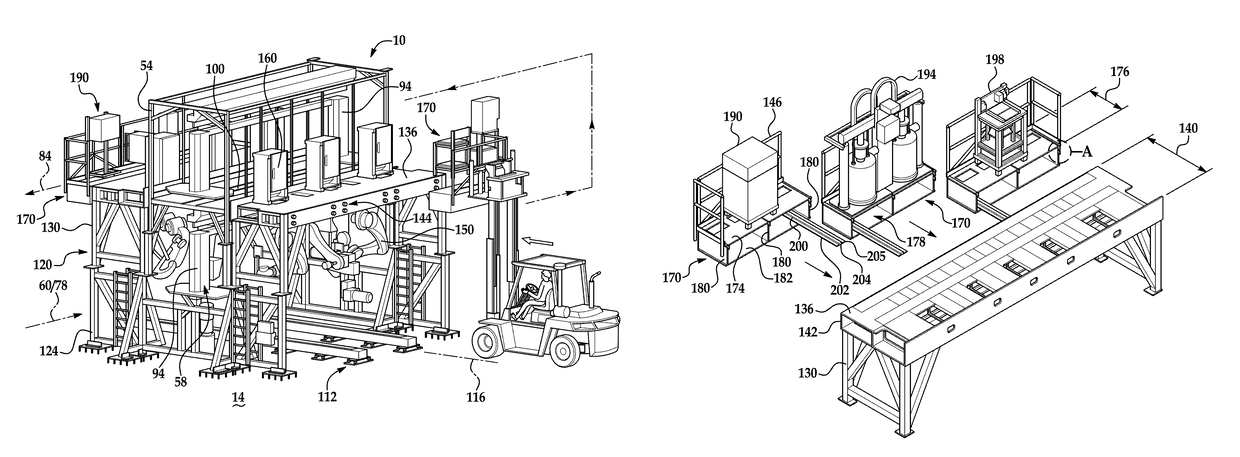
[0038]Examples of a modular vehicle assembly system and methods 10 are described below and illustrated in FIGS. 1-16. The exemplary assembly devices and systems are described as useful in high quantity assembling automotive passenger vehicles, but there are other applications for manufacturing and assembling other vehicles and products known by those skilled in the art.

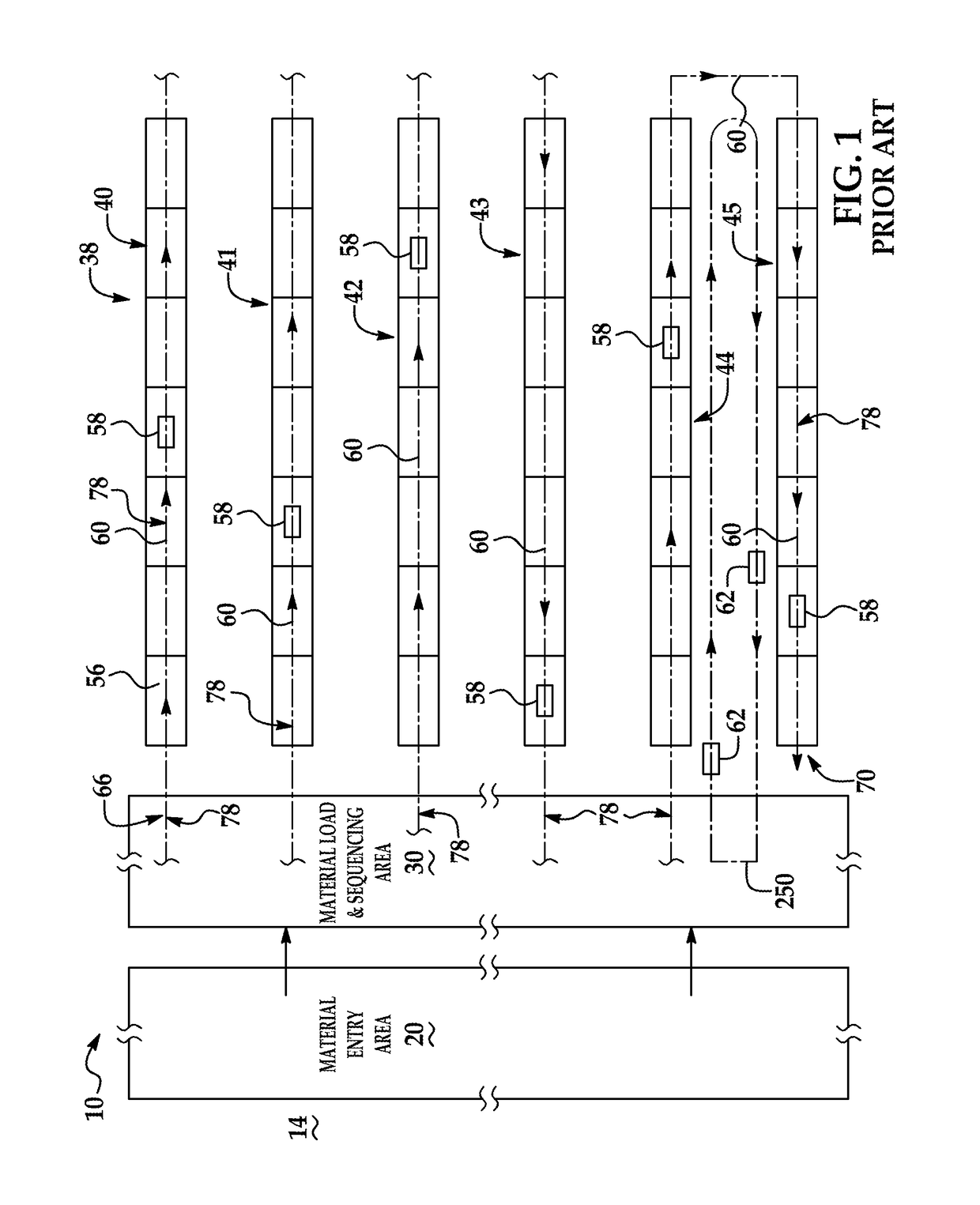
[0039]Referring to FIG. 1, a known vehicle assembly line for producing sheet metal skeletons of passenger vehicles known as “body-in-whites” (BIW) is shown on an assembly plant floor 14. In the example, a material entry area 20, a material loading and sequencing or staging area 30, and a plurality of assembly lines 38 (six shown in FIG. 1 and identified as 40-45 as illustrated). Each assembly line 38 includes a vehicle-in-process travel path 60 running down each line 40-45.

[0040]In the examples shown, two types of vehicle conveyors are particularly, but not exclusively, useful for transporting the partially completed ...


PUM

PropertyMeasurementUnit
widthaaaaaaaaaa
widthaaaaaaaaaa
widthaaaaaaaaaa

Abstract

A modular vehicle assembly system and methods for increased flexibility and adaptability of a high volume assembly facility which builds several vehicle models. In one example, the invention includes modular assembly equipment (AE) support pallets which are shipped to vendors for installation of selected AE equipment devices that are specific to a predetermined assembly operation and then validation tested prior to shipment. The modular AE pallets and AE devices are quickly installed and easily removable for maintenance or replacement. In other examples, modular AE support platforms and safety fencing are used to support ground level assembly operation and safer working environment.

Description

CROSS-REFERENCE TO RELATED APPLICATIONS[0001]This application claims priority benefit to U.S. Provisional Patent Application No. 62 / 091,687 filed Dec. 15, 2014 the entire contents of which are incorporated herein by reference.TECHNICAL FIELD[0002]The invention generally pertains to the field of product and vehicle assembly.BACKGROUND[0003]Traditional high volume manufacture and assembly of products, machines and vehicles has occurred in large assembly plants. These assembly plants have included multiple assembly lines where components are gathered, assembled and connected together. In the manufacture and assembly of vehicular bodies, the bodies typically include a skeleton of sheet metal components that are welded together through resistance spot welding, seam welding and brazing techniques to form what are commonly called “body-in-white” (BIW) structures.[0004]With the growing need to efficiently build vehicles and accommodate varying consumer demand, assembly plants have strived t...

Claims


Application Information

Patent Timeline
Patent Type & Authority Patents(United States)
IPC IPC(8): B62D65/02B23K11/11B23K37/047B23P21/00B23K11/30B23K101/00
CPCB62D65/022B23K11/115B23K11/3063B23K37/047B62D65/02B23P21/004B23K2101/06B23K2101/006B23P2700/50
Inventor KILIBARDA, VELIBOR
Owner COMAU LLC
Why Eureka
Try Eureka