Fan system having an external rotor
a technology of axial flow fans and rotors, which is applied in the direction of non-positive displacement fluid engines, axial flow pumps, non-positive displacement pumps, etc., can solve the problems of low production efficiency, high production cost, and inability to install axial flow fans reliably, and achieves simple assembly, high production efficiency, and reliable connection
- Summary
- Abstract
- Description
- Claims
- Application Information
AI Technical Summary
Benefits of technology
Problems solved by technology
Method used
Image
Examples
first embodiment
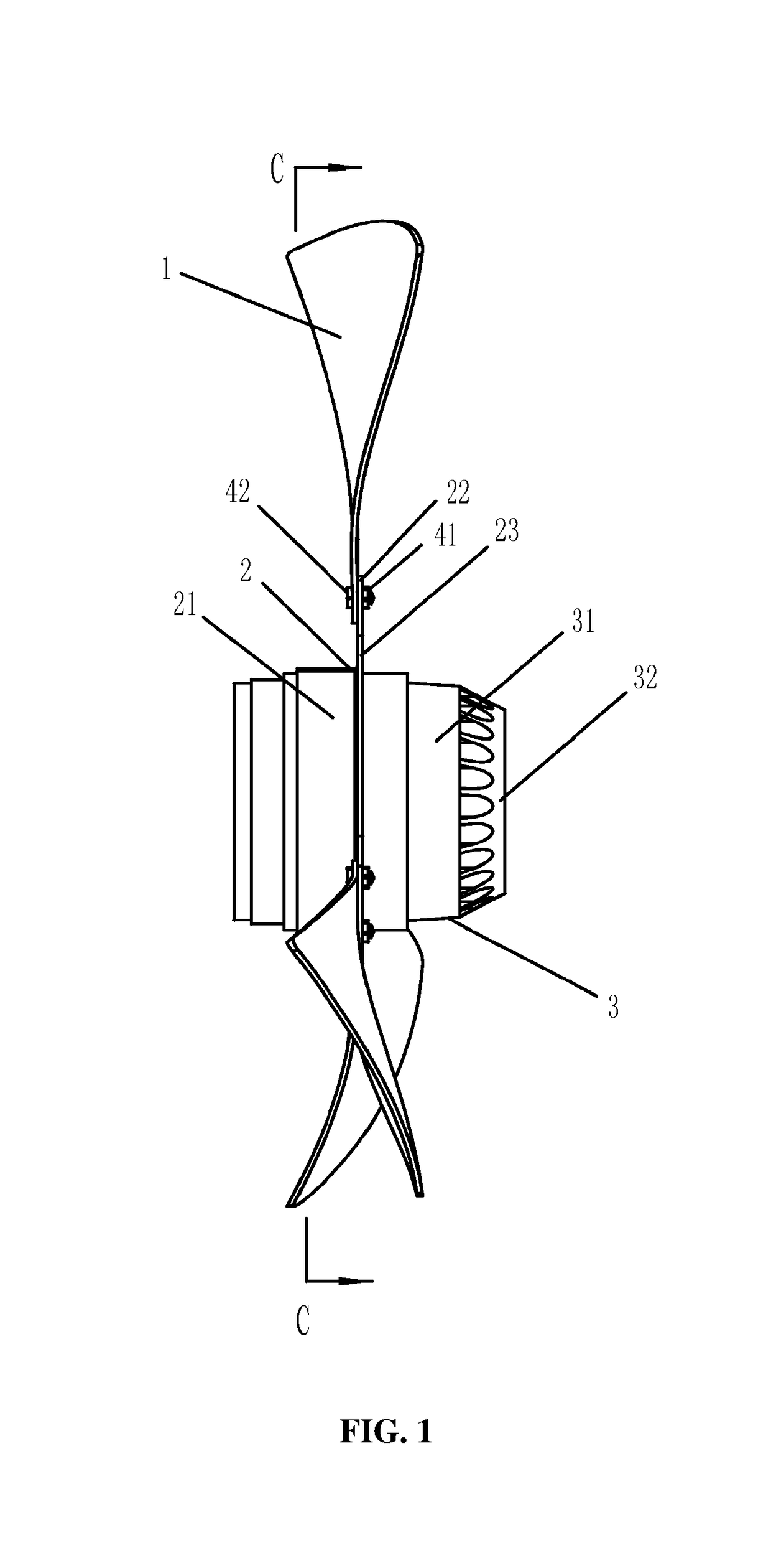
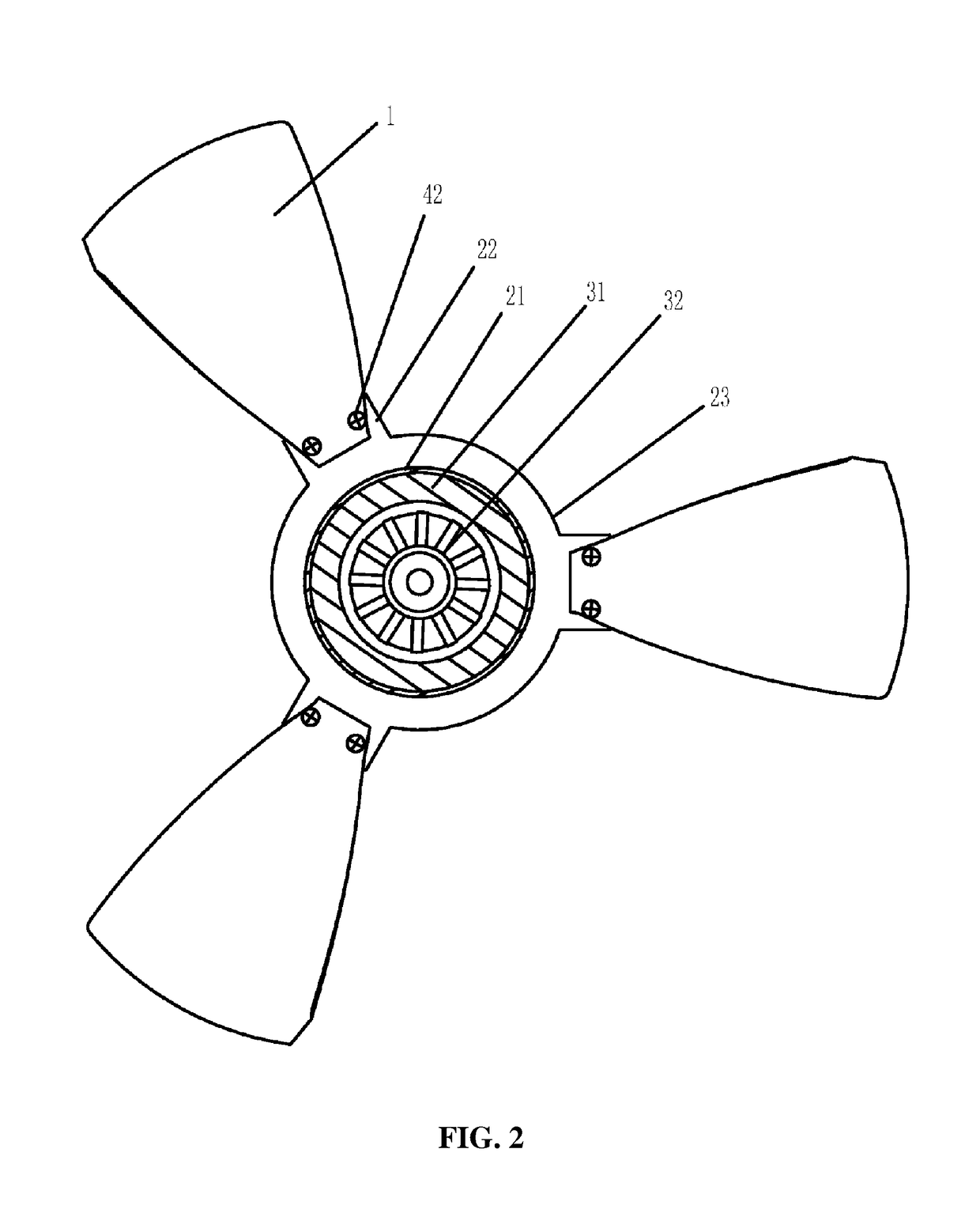
[0081]As shown in FIGS. 1 and 2, a fan system of the invention comprises an axial flow blade 1, a support 2 comprising an annular sleeve 21 and multiple installation pins 22, an external rotor motor 3 comprising an external rotor 31 and an inner stator 32, and an external convex ring 23.
[0082]The installation pins 22 are extended from the outside of the annular sleeve 21.
[0083]The axial flow blade 1 is disposed on the installation pin 22.
[0084]The annular sleeve 21 is fit on the external rotor 31 of the external rotor motor 3, and is integrally formed.
[0085]The external convex ring 23 is disposed between the annular sleeve 21 and the installation pin 22, and operates to increase radial dimension and to improve structural strength.
[0086]Inner wall of the annular sleeve 21 is interference-fit with outer wall of the external rotor 31.
[0087]A screw hole is disposed on the installation pin 22, and the axial flow blade 1 is disposed on the installation pin 22 via nuts 42 and bolts 41. The...
second embodiment
[0088]As shown in FIGS. 3 and 4, a fan system of the invention comprises an axial flow blade 1, a support 2 comprising a clamping element 21 and multiple installation pins 22, and an external rotor motor 3 comprising an external rotor 31 and an inner stator 32.
[0089]The installation pins 22 are extended from the outside of the clamping element 21.
[0090]The axial flow blade 1 is disposed on the installation pin 22.
[0091]The clamping element 21 is fit on the external rotor 31 of the external rotor motor 3, and is formed by an annular body having an opening via a fastening device 5 or via welding.
[0092]The inner wall of the clamping element 21 is interference-fit with the outer wall of the external rotor 31.
[0093]A screw hole is disposed on the installation pin 22, and the axial flow blade 1 is disposed on the installation pin 22 via nuts 42 and bolts 41. The clamping element 21 and the installation pin 22 are integrally formed.
third embodiment
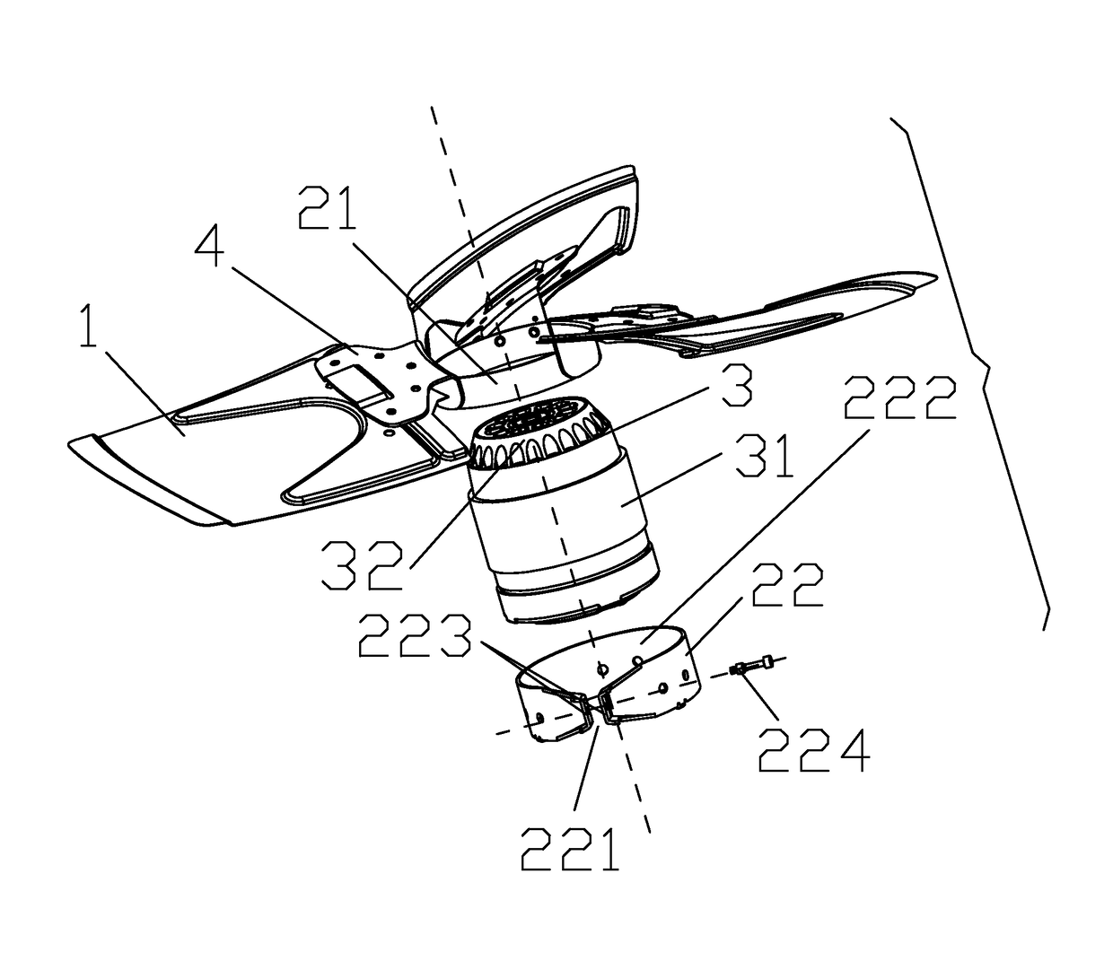
[0094]As shown in FIGS. 5-7, a fan system of the invention comprises multiple axial flow blades 1, a support comprising a first part and a second part, an external rotor motor 3 comprising an external rotor 31 and an inner stator 32.
[0095]The first part comprises an annular sleeve 21 and multiple installation pins 4. The second part is a clamping element 22. The first part is connected to the second part, both the first part and the second part are fit on the external rotor 31, and the support encloses the outer wall of the external rotor 31. The installation pins 4 are extended from the outside of the annular sleeve 21, and the multiple axial flow blades 1 are respectively disposed on the installation pins 4.
[0096]An end of the annular sleeve 21 is welded to an end of the clamping element 22 and a welding line 23 is formed between the annular sleeve 21 and the clamping element 22.
[0097]The inner wall of the annular sleeve 21 is interference-fit with the outer wall of the external r...
PUM
 Abstract
Description
Claims
Application Information
 - R&D
- Intellectual Property
- Life Sciences
- Materials
- Tech Scout
- Unparalleled Data Quality
- Higher Quality Content
- 60% Fewer Hallucinations
Browse by: Latest US Patents, China's latest patents, Technical Efficacy Thesaurus, Application Domain, Technology Topic, Popular Technical Reports.
© 2025 PatSnap. All rights reserved.Legal|Privacy policy|Modern Slavery Act Transparency Statement|Sitemap|About US| Contact US: help@patsnap.com


