Method and device for determining whether an error condition is present or not in a motor vehicle

a technology of error condition and motor vehicle, which is applied in the direction of vehicle sub-unit features, testing/monitoring control systems, instruments, etc., can solve the problems of high development complexity of corresponding monitoring functions, complex concept, and often traced development complexity, and achieve significant increase in the error coverage ratio

Inactive Publication Date: 2018-11-27
ROBERT BOSCH GMBH
View PDF6 Cites 0 Cited by
  • Summary
  • Abstract
  • Description
  • Claims
  • Application Information

AI Technical Summary

Benefits of technology

[0008]By using the provided method, errors may be identified particularly easily by the presence of an unacceptable state and counter measures may be initiated.
[0009]The provided method has the advantage that it is particularly easily reusable and scalable, i.e., that it may be expanded particularly easily to other motor vehicle topologies, such as, for example, a hybridized drivetrain. By transferring the operating state into an acceptable state, the method is particularly reliable.
[0010]In another aspect, it may be provided that, depending on the ascertained discrete state, a continuous actual operating parameter, which describes an operating state of the motor vehicle, is ascertained or not. Due to this ascertainment, it is possible that additional information is ascertained about the operating state of the motor vehicle, and thus the method is even more reliable.
[0017]In this way, it is possible in a particularly easy way to expand the monitoring of the operating state of the motor vehicle to continuous variables. From the interplay of the state machine and the use of the continuous actual operating parameters, the result arises that the system is intact or that a defect is present, and this defect has been detected by the presence of an unacceptable state in the state machine, or that the defect has been detected as a function of the continuous actual operating parameter. The error coverage ratio is significantly increased by the latter measure.

Problems solved by technology

Such a concept is, however, complex, since a change in the control software of the drivetrain or in the application entails a change in the monitoring software.
Due to the electrification of the vehicle drivetrains, the drivetrain variance, the number of safety objectives, and thus also has the development complexity of the corresponding monitoring functions strongly increased.
This development complexity is often traced back to the limited reusability of existing error mechanisms in new drivetrain variants.

Method used


Image

  • Method and device for determining whether an error condition is present or not in a motor vehicle
  • Method and device for determining whether an error condition is present or not in a motor vehicle
  • Method and device for determining whether an error condition is present or not in a motor vehicle

Examples


Embodiment Construction

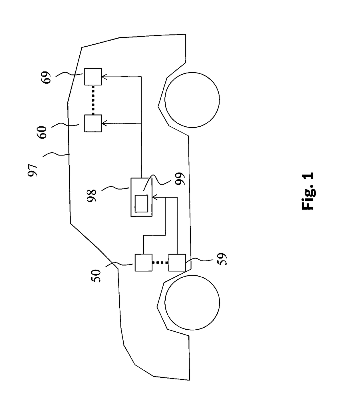
[0026]FIG. 1 shows a motor vehicle 97 in which the present invention may be used. The method may, for example, be carried out by a control unit 98, in particular carried out by a computer program which is stored on a machine-readable storage medium 99 which is contained in control unit 98. Control unit 98 hereby receives signals from sensors 50 . . . 59 in a known way and controls actuators 60 . . . 69 on the basis of these sensor signals.

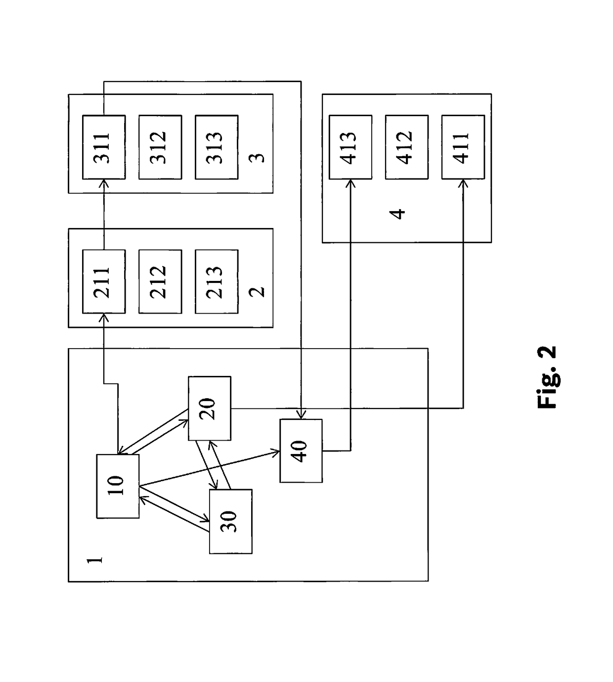
[0027]FIG. 2 shows a structure diagram which illustrates how the method according to the present invention may progress according to one aspect of the present invention. State machine 1, which includes states 10, 20, 30, is provided. Depending on the ascertained sensor values of sensors 50 . . . 59, state transitions are defined, which transfer state machine 1 from the present state, for example, state 20, into another state, for example, state 10. These states 10, 20, 30 are either acceptable or unacceptable. If the present state, for example stat...


PUM


Abstract

A method for determining whether an error is present or not in a motor vehicle, a discrete state, in which the motor vehicle is presently in, being ascertained with the aid of a state machine, a decision being made, depending on the ascertained discrete state, whether an error is present or not, whereby the states of the state machine include acceptable states and unacceptable states, then, if the ascertained discrete state is an unacceptable state, the motor vehicle is transferred into an acceptable state.

Description

RELATED APPLICATION INFORMATION[0001]The present application claims priority to and the benefit of German patent application no. 10 2015 215 546.3, which was filed in Germany on Aug. 14, 2015, the disclosure of which is incorporated herein by reference.FIELD OF THE INVENTION[0002]The present invention relates to a method for determining whether an error condition is present or not in a motor vehicle, in particular in the drive system of the motor vehicle. The present invention furthermore relates to a device, in particular a control unit, which is configured to carry out this method.BACKGROUND INFORMATION[0003]A method for controlling the drive output of a vehicle is discussed in DE 44 38 714 A1, in which a microcomputer is provided to carry out control functions and monitoring functions. At least two levels independent from one another are thereby established in the microcomputer, a first level carrying out the control function and a second level carrying out the monitoring functio...

Claims


Application Information

Patent Timeline
Patent Type & Authority Patents(United States)
IPC IPC(8): G07C5/08G05B17/02
CPCG07C5/0816G05B17/02B60Y2306/15B60Y2200/92B60K28/10B60W40/12B60W2050/0019B60W2530/00B60W2710/06F16H61/12F16H2061/1208G05B23/0248
Inventor PATINO, ISIDRO CORRALBALLMANN, EVGENIYAMUELLER, BERNDGRIMM, ANDREAS
Owner ROBERT BOSCH GMBH
Why Eureka
Try Eureka