Obstacle detection system

a detection system and obstacle technology, applied in the field of obstacles detection systems, can solve the problems of reducing the accuracy of the vehicle wheel speed sensor, affecting the accuracy of the vehicle speed detection value, and the likelihood of errors in the measured values of the vehicle speed and rudder angle, so as to eliminate the false detection of obstacles and achieve the effect of high degree of accuracy

Inactive Publication Date: 2009-06-23
HITACHI LTD
View PDF1 Cites 18 Cited by
  • Summary
  • Abstract
  • Description
  • Claims
  • Application Information

AI Technical Summary

Benefits of technology

[0004]Therefore, there is a case where if a detection error of the vehicle speed or that of the rudder angle occurs, an error occurs in the estimated image, which may result in the fact a planar pattern is detected as a three-dimensional object. It is to be noted that measured values of the vehicle speed and rudder angle are likely to contain an error due to a change in air pressure of tires, the abrasion of rubber, slips, and the like. In particular, at the time of low-speed driving, for example, during when a vehicle is moved to be stored into a garage, the accuracy of a vehicle wheel speed sensor decreases, and thereby an error will easily occur in a detection value of the vehicle speed.
[0006]It is possible to detect a three-dimensional object by use of a single-eyed camera with a higher degree of accuracy by eliminating false detection of an obstacle, which is caused by a detection error of a vehicle speed sensor or that of a rudder angle sensor.

Problems solved by technology

Therefore, there is a case where if a detection error of the vehicle speed or that of the rudder angle occurs, an error occurs in the estimated image, which may result in the fact a planar pattern is detected as a three-dimensional object.
It is to be noted that measured values of the vehicle speed and rudder angle are likely to contain an error due to a change in air pressure of tires, the abrasion of rubber, slips, and the like.
In particular, at the time of low-speed driving, for example, during when a vehicle is moved to be stored into a garage, the accuracy of a vehicle wheel speed sensor decreases, and thereby an error will easily occur in a detection value of the vehicle speed.

Method used


Image

  • Obstacle detection system
  • Obstacle detection system
  • Obstacle detection system

Examples


first embodiment

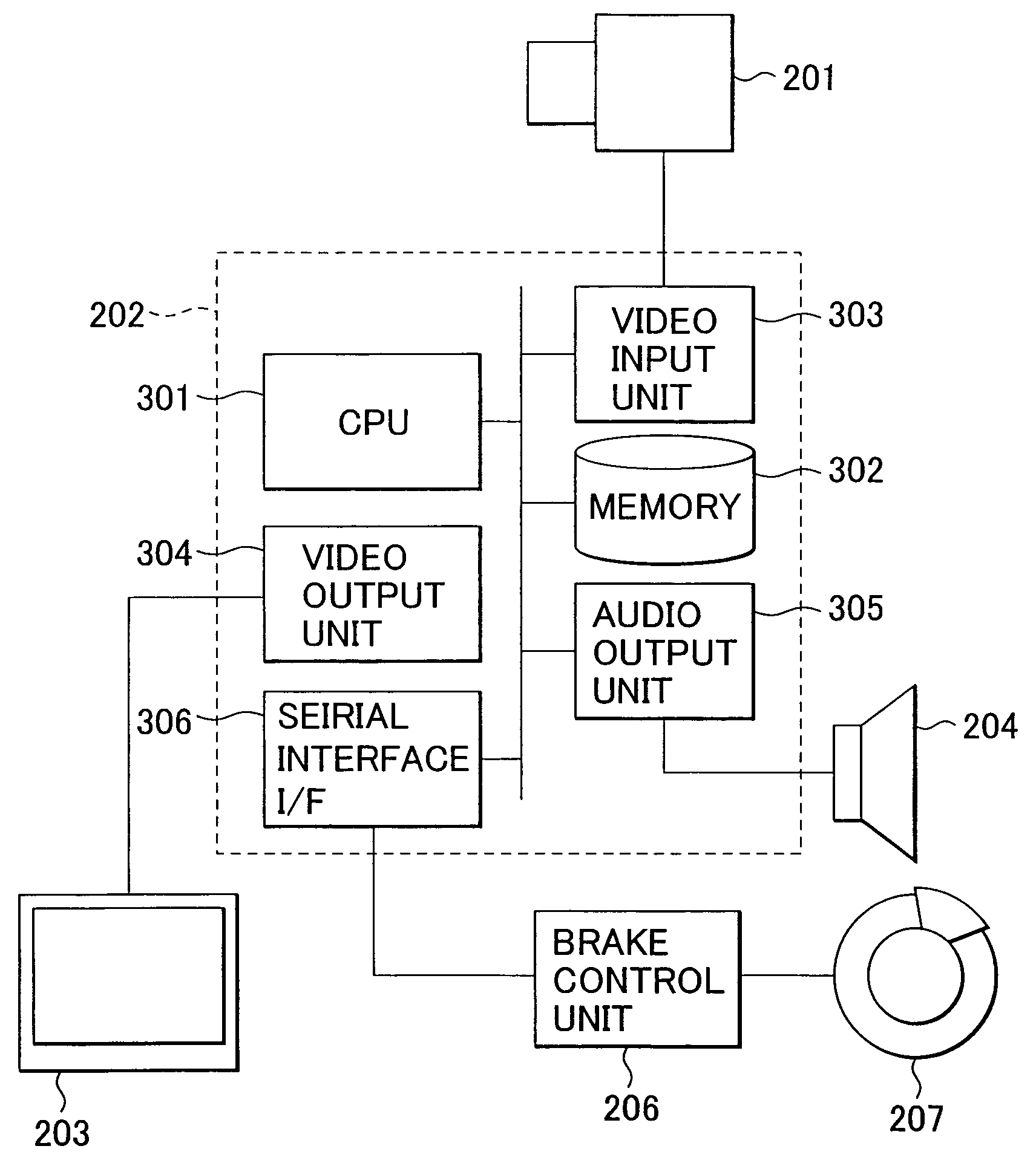
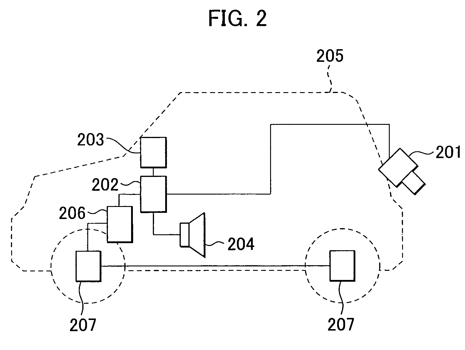
[0020]FIG. 2 is a diagram illustrating a configuration of a vehicle that is equipped with an obstacle detection system. A camera 201 is mounted to the rear of the vehicle 205. This camera 201 is located with such a depression angle that the optical axis of a lens is oriented in an obliquely downward direction. A video image is taken by this camera 201 as an oblique overhead view. Image data which is imaged by the camera 201 is inputted into a processing unit 202 through a communication line 209. The processing unit 202 identifies an obstacle by means of the undermentioned image processing. The processing unit 202 is connected to an image display unit 203 through a signal line. The processing unit 202 displays various kinds of information about the obstacle, the information including an image imaged by the camera 201, and the positional relationship between the detected obstacle and the host vehicle. In addition, the processing unit 202 is also connected to an audio output unit 204. ...

second embodiment

[0049]Up to this point, the embodiment which uses white lines was described as a method for associating two images with each other. In the case of an outdoor parking space or a multistory parking space, white lines are drawn on the road surface in many cases. Accordingly, it is possible to associate images with each other by using each of the white lines as a landmark. However, in the case of a home garage where only one car is parked, in many cases white lines are not drawn on the road surface. In such a case, it is necessary to find out a landmark other than the white line. An embodiment in which no white line is drawn will be described as below.

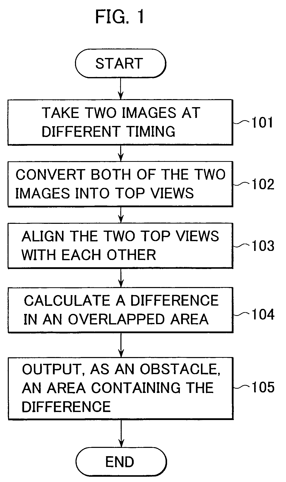
[0050]Incidentally, a configuration of the vehicle 205 and that of the processing unit 202 in this embodiment are the same as those illustrated in FIGS. 2, 3. In addition, the process flow in this embodiment is also the same as that illustrated in FIG. 1 except processing of associating each position of one image with each corresponding po...


PUM


Abstract

An object of the present invention is to detect a three-dimensional object by use of a single-eyed camera with a higher degree of accuracy by eliminating false detection of an obstacle, which is caused by a detection error of a vehicle speed sensor or that of a rudder angle sensor.A top view of a first image including a road surface image is created. The first image is imaged by a camera mounted to a vehicle. Then, a top view of a second image is created. The second image is imaged at a timing different from the timing when the first image is imaged. The two top views are associated with each other on the basis of a characteristic shape on the road surface. In each overlapped portion of the two top views, an area in which a difference occurs is identified as an obstacle.

Description

BACKGROUND OF THE INVENTION[0001]The present invention relates to an obstacle detection system for detecting, by use of a camera mounted to a vehicle, an obstacle that hinders the driving of the vehicle.[0002]Heretofore, the stereoscopic vision technology for identifying a three-dimensional object by the principles of triangular surveying on the basis of a parallax error of images obtained from two cameras is known. However, stereoscopic cameras are in general more expensive than single-eyed cameras. For this reason, the technique as disclosed in JP-A-10-222679 is known as a technology for identifying a three-dimensional object by a single-eyed camera.SUMMARY OF THE INVENTION[0003]According to the above-described prior art, from a currently acquired image, an estimated image in the next image acquisition timing is created by use of the speed and rudder angle of a vehicle which are acquired from a vehicle speed sensor and a rudder angle sensor respectively. Then, by comparing the est...

Claims


Application Information

Patent Timeline
Patent Type & Authority Patents(United States)
IPC IPC(8): B60Q1/00
CPCB60R21/0134G06T7/0022G06T7/0042G06T7/2053G06K9/00798G06K9/00805B60R2021/01259G06T2207/30261G06T7/97G06T7/73G06T7/254G06V20/588G06V20/58
Inventor OTSUKA, YUJIMURAMATSU, SHOJIMONJI, TATSUHIKO
Owner HITACHI LTD
Why Eureka
Try Eureka