Floating solar panel systems

a solar panel and solar panel technology, applied in the field of photovoltaic systems, can solve the problems of negative environmental impact and huge land area, and achieve the effects of reducing wave motion, reducing wave motion inside the buoy, and reducing wave motion

Inactive Publication Date: 2018-11-27
4CSOLAR
View PDF28 Cites 21 Cited by
  • Summary
  • Abstract
  • Description
  • Claims
  • Application Information

AI Technical Summary

Benefits of technology

[0008]This application presents a floating device allowing solar photovoltaic panels to float on the sea surface with reduced wave motions. The solar panels are self-supported thanks to one or several extruded floats, such as polystyrene, attached on the bottom side of the panels. The wave motions are reduced thanks to a float around the solar array, made of a combination of a buoy or pontoon and a skirt. The buoy can have a circular or polygonal peripheral shape. The buoy can be constituted of a unique buoy, or by the association of several buoys (for example, 4 buoys for a rectangular or square shaped buoy, or 8 buoys for an octagonal shaped buoy). The buoy can be inflatable, or made of one or several high density tubes, such as polyethylene, equipped or not with additional floating devices used typically for dredging applications. The float has also a relatively rigid skirt around it to allow the float to behave like a “moon pool” device, and thus to reduce wave motions inside the buoy. The skirt is weighted to remain substantially vertical in the water and form a barrier around the column of water so as to create a calm sea with highly reduced waves within the peripheral shape and prevents the wind from lifting up the buoy. The rigidity of the skirt can be attained, for example, with horizontal and vertical tubes inserted in the skirt. The photovoltaic panels will be either floating on the sea water in a horizontal position, held with cables and brackets, or in an inclined position to angle the panels toward the sun.
[0012]An alternative floating solar system comprises a border pontoon adapted to float on water defining a closed peripheral shape surrounding an interior space. An array of interconnected photovoltaic panels are structurally connected together within the peripheral shape, each photovoltaic panel having a flotation device secured thereto so that the array is at least partially buoyant, the photovoltaic panels being electrically connected. A stabilizing skirt depends downwardly from the border pontoon to surround a column of water underneath the array of photovoltaic panels, the skirt having a plurality of struts supporting solid vertical panels therebetween. The struts are made of a material having a higher density than water, and the skirt thus forms a barrier around the column of water and creates a more stable volume of water within the peripheral shape that outside of the border pontoon.

Problems solved by technology

During the next decades, the generation of sustainable energy will become one of the main challenges of our civilization.
Wind farms, hydroelectric power plants, thermal power stations, and solar power plants all need a certain area of land, which is costly and can negatively affect the environment.
However, for solar power plants to offer the same generating capacity and supply stability as traditional power plants, the required land area is enormous.

Method used


Image

  • Floating solar panel systems
  • Floating solar panel systems
  • Floating solar panel systems

Examples


Embodiment Construction

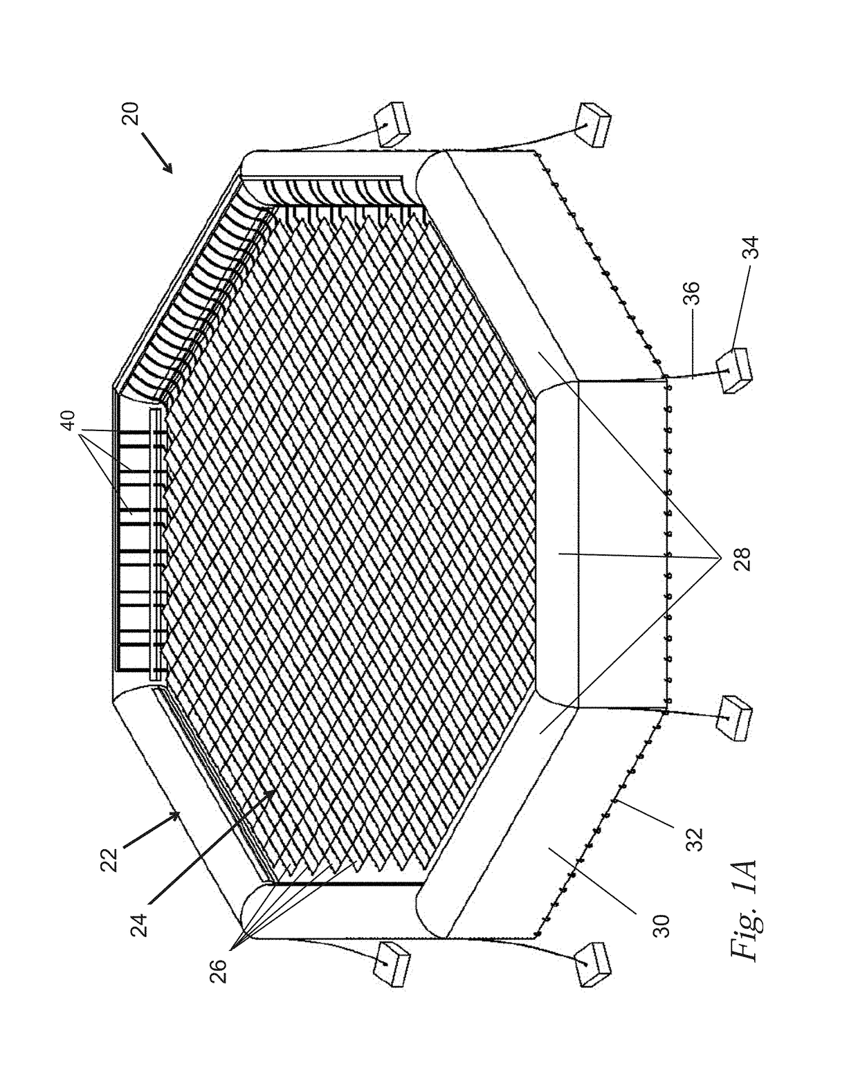
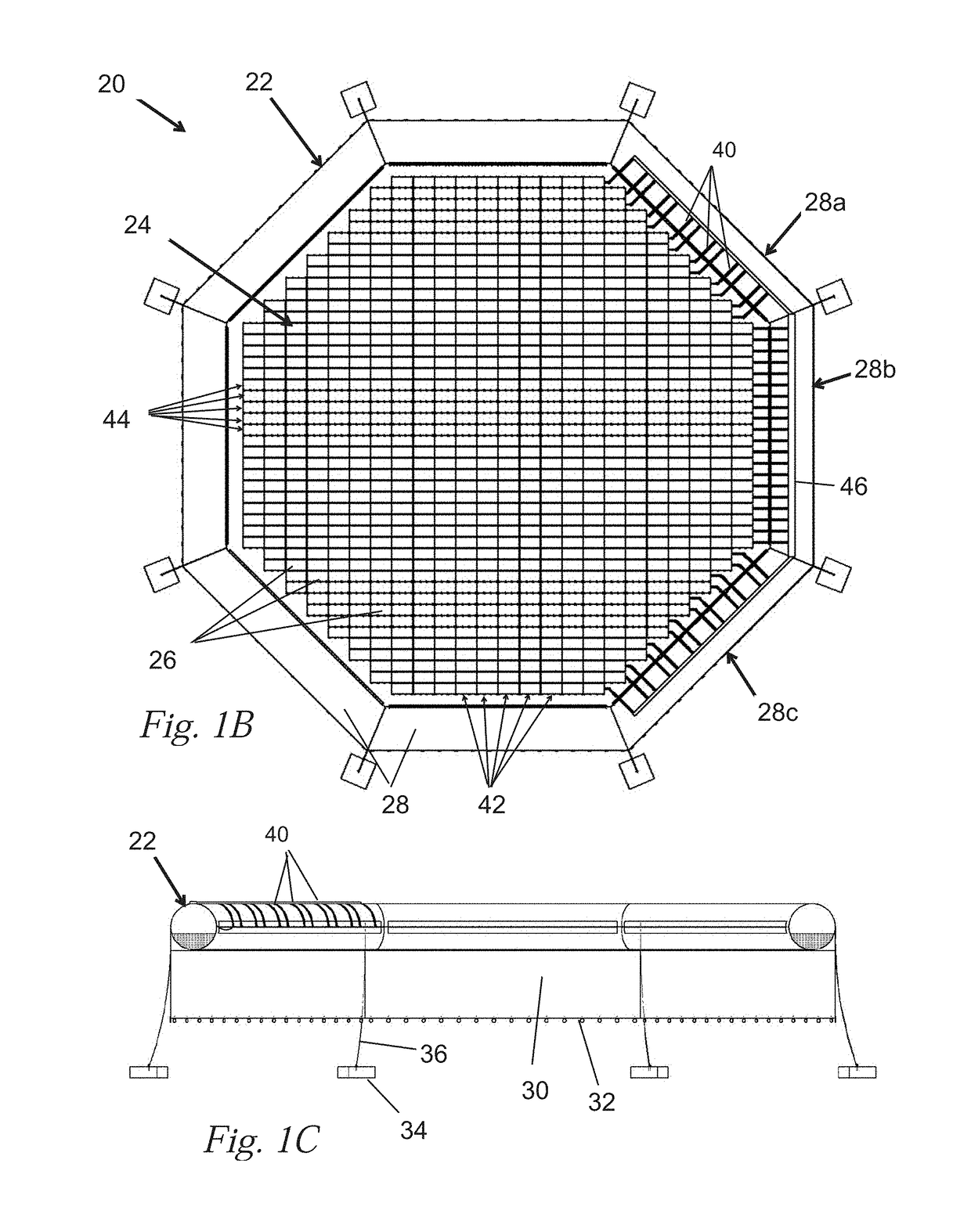
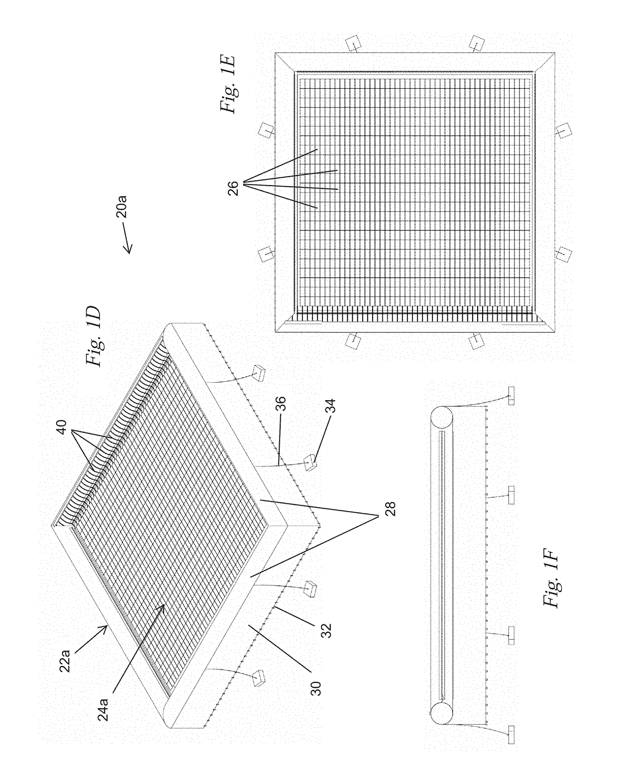
[0035]The present application discloses a number of floating solar units or systems each having a peripheral buoyant pontoon within which is suspended an array of individual photovoltaic panels. A stabilizing skirt drops down into the water underneath the pontoon and creates a more placid “moon pool” within the pontoon to reduce turbulence from wave action and therefore enhance the efficiency of the array of photovoltaic panels. A plurality of the floating solar systems may be aggregated to form an island of units. It should be understood that the various aspects of the floating solar systems may be interchanged and combined in many ways, and that none are excluded. The scope of the invention being defined only by the appended claims.

[0036]The floating solar systems may be deployed in any body of water large enough to receive them. The size of the units may vary from relatively small (10 meters wide) to quite large. An exemplary floating solar system has an outer diameter of about 4...


PUM


Abstract

A floating solar system having a peripheral buoyant pontoon within which is suspended an array of individual photovoltaic panels each equipped with a float. A stabilizing skirt drops down into the water underneath the pontoon and creates a more placid “moon pool” within the pontoon to reduce turbulence from wave action and therefore enhance the efficiency of the array of photovoltaic panels. A plurality of the floating solar systems may be aggregated to form an island of units. The individual panels or rows or columns thereof may be flat (horizontal) or tilted so that they can be oriented more normally with regard to the sun's rays.

Description

RELATED APPLICATIONS[0001]The present application claims priority under 35 U.S.C. § 119 to U.S. Provisional Ser. No. 62 / 086,146, filed Dec. 1, 2014.FIELD OF THE INVENTION[0002]The present application pertains to photovoltaic systems and, more particularly, to systems of floating solar panels and floats therefor that reduce wave motion.BACKGROUND OF THE INVENTION[0003]During the next decades, the generation of sustainable energy will become one of the main challenges of our civilization. Worldwide energy demand is expected to grow from about 10 GTep (1010 Tep [Ton Equivalent Petrol], or 5*1019 Joule) in the beginning of the century to 15-20 GTep by 2050. Some scenarios predict even levels as high as 40 GTep. An analysis of future global petrochemical consumption needs (i.e. energy needs and / or raw material for chemical industry) implies that early petrol shortages might already appear in the mid of the century. The need for large scale renewable energy sources is underlined by the gl...

Claims


Application Information

Patent Timeline
Patent Type & Authority Patents(United States)
IPC IPC(8): H01L31/042B63B35/44H02S20/00H02S30/10H02S40/36B63B7/08
CPCH02S20/00B63B7/08B63B35/44H02S40/36H02S30/10Y02E10/50B63B2035/4453
Inventor SMADJA, LILIANESMADJA, PAUL ISAAC
Owner 4CSOLAR
Why Eureka
Try Eureka