
Method and apparatus for manufacturing an insulation panel

a technology of insulation panels and manufacturing methods, applied in heat proofing, other domestic objects, chemistry apparatus and processes, etc., can solve the problems of restricting the application of insulation panels in construction applications, vacuum insulation panels on a factory scale, etc., to reduce the risk of air entrapment, uniform thickness, and enhance the effect of compaction

Active Publication Date: 2018-12-04
KINGSPAN HLDG (IRL) LTD
View PDF18 Cites 0 Cited by
  • Summary
  • Abstract
  • Description
  • Claims
  • Application Information

AI Technical Summary

Benefits of technology

[0003]Current VIP technology generally comprises a single panel of insulation material formed typically of fumed silica, fibre and / or other microporous material core, which may or may not contain infra red opacifiers, the core wrapped in a flexible, gas-tight envelope and a vacuum applied before sealing. The vacuum is essential to the panel's thermal insulating performance. Thermal conductivity properties of VIPs are typically of the order of 0.005 W / mK. If the vacuum is lost the panel loses a large proportion of its effectiveness as a thermal insulator, with the thermal conductivity reverting to that of the core material, which is typically above 0.020 W / m.K. To reduce the effects of damage to an insulation system, it is therefore useful to divide a VIP into smaller compartments. The advantage is that loss of vacuum in one compartment will not affect adjacent compartments.
[0004]The use of VIP technology in construction is not widespread but could enable improved insulation properties and allow a significant reduction in thickness of insulation materials required to meet ever increasing requirements for thermal efficiency of buildings.
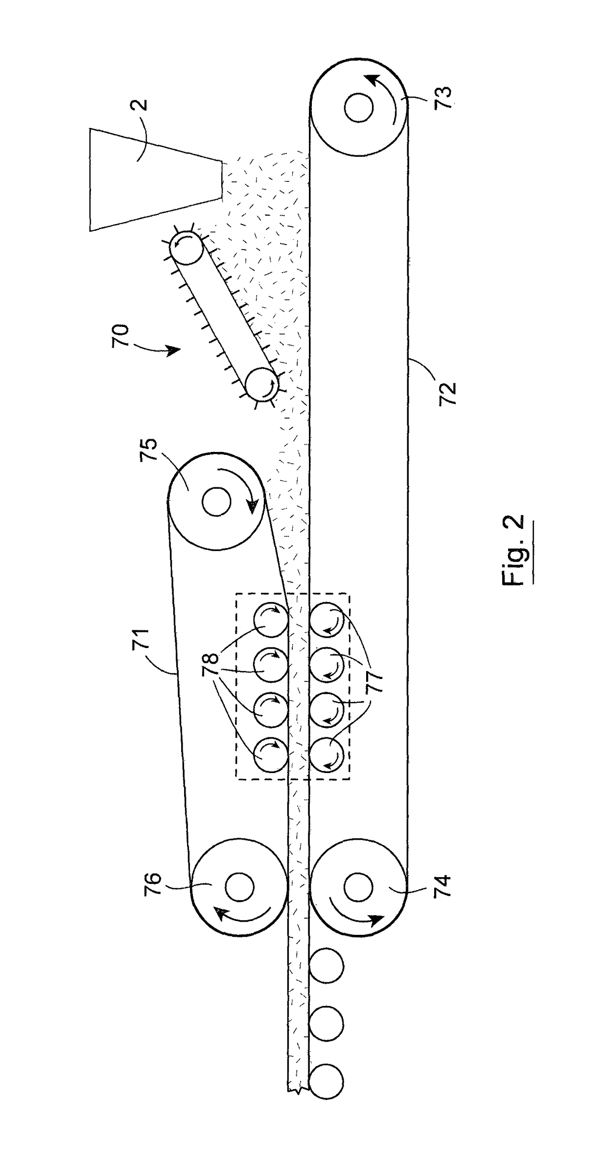
[0014]The process preferably comprises pressing the material in a number of stages to progressively press the material from an initial thickness to a smaller thickness. This feature enhances the compaction on a continuous basis.
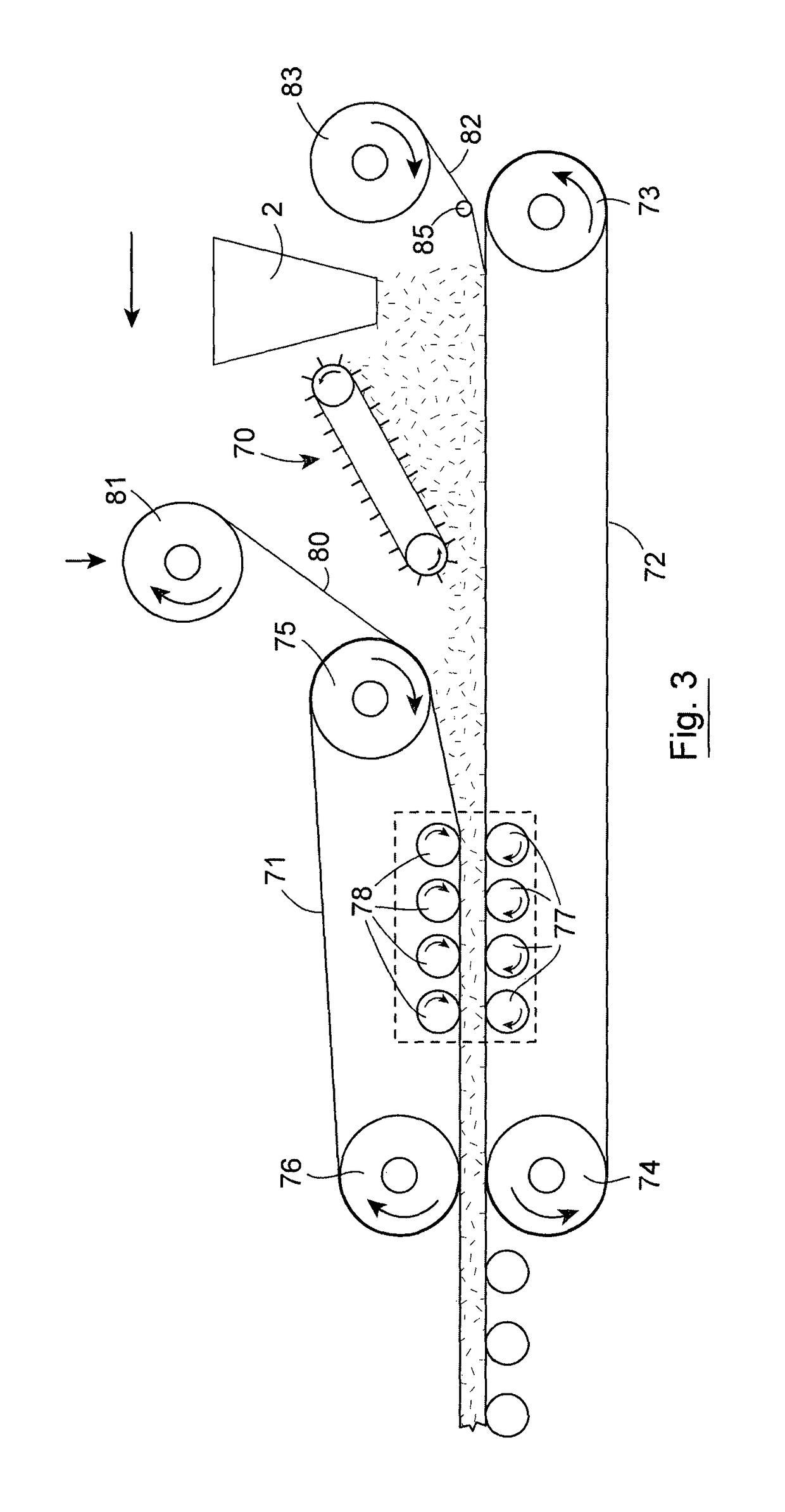
[0015]In one case the system comprises a pre-compression step which may be provided by additional rollers. This gives the advantage of a longer more gradual de-aeration of the mixture prior to entering the main pressing zone. In the case where an air permeable sheet such as a fleece material is applied additional air can escape through the fleece. This reduces the risk of air entrapment and facilitates optimisation of the line speed with increased output.
[0031]Preferably the pressing means progressively compacts the material in a number of stages from an initial thickness to a smaller thickness and provides a continuous sheet of pressed insulation core material of substantially uniform thickness. This feature enhances the compaction on a continuous basis.
[0032]In one case the system comprises a pre-compression zone which may be provided by additional rollers applied. This gives the advantage of a longer more gradual de-aeration of the mixture prior to entering the main pressing zone. In the case where an air permeable sheet such as a fleece material is applied additional air can escape through the fleece. This reduces the risk of air entrapment and facilitates optimisation of the line speed with increased output.

Problems solved by technology

The production of such vacuum insulation panels on a factory scale is a challenge that restricts the application of such panels in construction applications.

Method used


Image

  • Method and apparatus for manufacturing an insulation panel
  • Method and apparatus for manufacturing an insulation panel
  • Method and apparatus for manufacturing an insulation panel

Examples


Embodiment Construction

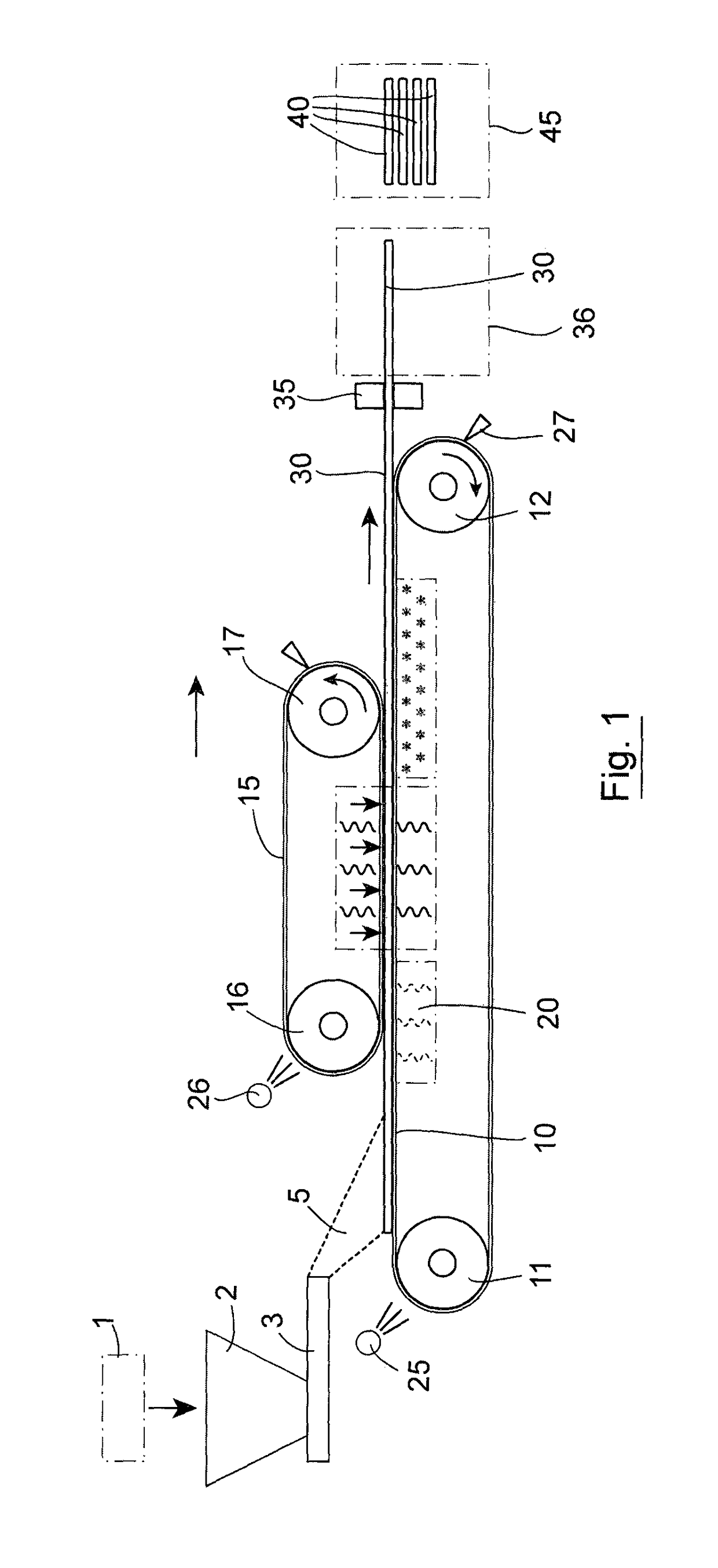
[0049]Referring to the drawings, there is illustrated apparatus for manufacturing vacuum insulation panels 60 on a factory scale. The invention provides equipment and methods for continuous mass production of the core materials for such vacuum insulation panels. The invention enables a continuous compressed core to be formed and easily cut into smaller sections.

[0050]A microporous insulation material mixture to form an insulation core may comprise any suitable insulating material such as pressed fumed silica premixed with fibres and IR opacifier. If the insulating material is in the form of particulates, the particulates may be bound together to facilitate forming into a described shape, for example using a suitable binder. The mixture may for example, comprise fumed silica, IR opacifier, and fibres of organic or inorganic material.

[0051]Referring initially to FIG. 1 the mixture is blended in a blender 1 and on demand, the blended mixture is delivered on a continued or batch basis i...


PUM

PropertyMeasurementUnit
thermal conductivityaaaaaaaaaa
thicknessaaaaaaaaaa
sizeaaaaaaaaaa

Abstract

A microporous insulation material mixture is blended and the blended mixture is spread across a lower conveyor belt which is trained over rollers. To aid the spreading of the mixture a spreading device is used. The mixture is delivered by the conveyor to a pressing system which in this case comprises an upper conveyor belt. The pressing system also comprises a nipping means provided in this case by a plurality of upper and lower nipping rollers. The gaps between the individual rollers are adjustable. An upper fleece liner is led from a delivery roller to lie between the upper conveyor belt and the insulation mixture and a lower fleece liner is fed from a delivery roller to lie between the insulation mixture and the lower conveyor belt. The fleece liners may be used to encase the core prior to enclosing in an envelope and applying a vacuum.

Description

[0001]This is a national stage of PCT / IE12 / 00033 filed Jun. 27, 2012 and published in English, which has a priority of Irish no. 2011 / 0301 filed Jun. 27, 2011, hereby incorporated by reference.INTRODUCTION[0002]This invention relates to vacuum insulation panels (VIP).[0003]Current VIP technology generally comprises a single panel of insulation material formed typically of fumed silica, fibre and / or other microporous material core, which may or may not contain infra red opacifiers, the core wrapped in a flexible, gas-tight envelope and a vacuum applied before sealing. The vacuum is essential to the panel's thermal insulating performance. Thermal conductivity properties of VIPs are typically of the order of 0.005 W / mK. If the vacuum is lost the panel loses a large proportion of its effectiveness as a thermal insulator, with the thermal conductivity reverting to that of the core material, which is typically above 0.020 W / m.K. To reduce the effects of damage to an insulation system, it ...

Claims


Application Information

Patent Timeline
Patent Type & Authority Patents(United States)
IPC IPC(8): E04B1/76B29C43/26B29C43/28B29C43/48E04B1/80B29C43/34
CPCE04B1/7658B29C43/26B29C43/28B29C43/48E04B1/803Y02B80/12B29C2043/3427B29C2043/483Y02A30/242Y02B80/10B32B37/1027B32B2307/304B32B2264/102B32B2309/68B32B2309/105B32B5/26B32B2607/02
Inventor ROCHEFORT, MALCOLMPARGETER, ADRIAN
Owner KINGSPAN HLDG (IRL) LTD
Learn More