Rear Deploying Broadhead

a rear-deploying, broadhead technology, applied in the field of archery, can solve the problems of not being identical in weight and size to each other, not being able to shoot from a bow with a light weight, and being expensive, so as to reduce the impact value, reduce the molecular weight, and reduce the tensile strength

Active Publication Date: 2022-08-04
MOTZ TROY ALLEN
View PDF46 Cites 0 Cited by
  • Summary
  • Abstract
  • Description
  • Claims
  • Application Information

AI Technical Summary

Benefits of technology

[0029]In the present invention, an overcured coating is desirable, as it reduces the impact value. Similarly, use of a coating with a relatively lower molecular weight results in lower tensile strength and thus, lower impact value. Lower or controlled use of plasticizers will provide for better control of the flexibility, formability, and impact resistance of coating films. Some applications require flexibility and impact resistance at low temperatures. Impact resistance can be significantly improved at increased plasticizer levels, as well as being a function of the plasticizer type. The flexibility and toughness of coatings are also dependent on temperature. High temperatures may cause the coating to bake or cure excessively. It causes the coating to become brittle with decreased impact resistance, or it may become more resistant to the environment than would occur if it were only air-dried under ambient conditions. Also, coatings at a temperature below glass transition temperature (Tg) are hard and brittle with poor flexibility and impact resistance unless there is an auxiliary loss mechanism below Tg or below the temperature at which the coating is used. Such coatings are desirable, so long as the other necessary properties of the coating are attained.

Problems solved by technology

Carbon shafts have the advantage that they do not bend or warp, but they can often be too light weight to shoot from some bows and are expensive.
Wood shafts are the least expensive option but often will not be identical in weight and size to each other and break more often than the other types of shafts.
The flight of prior art broadheads in which the blades are secured on the arrow in a fully open position was adversely affected by wind resistance acting against the exposed broadhead blades.
Accordingly, broadheads with fixed blades tend to be less accurate because of wind current deflection and tend to have less velocity because of increased drag.
However, by reducing the surface area of a blade, the cutting area within a target or game is also reduced, resulting in a less effective entrance and exit wound.
Unfortunately, these blade-opening arrowheads are often complex mechanically and include a significant force holding the blades close.
This significant force can be difficult to overcome, and these devices may fail to open reliably.
Others have structural defects within the body that can result in premature opening of the blade.
These conventional annular retaining rings are prone to cracking, particularly when the elastomer material dries out.
The conventional annular retaining rings counteract the opening forces, but fail of the ring material is brittle or damaged.
In addition to the cost involved with supplying such consumable item, the annular retaining rings are difficult and time-consuming to install, such as when hunting, particularly during inclement weather.
Furthermore, the material properties of such conventional annular retaining rings can be affected by temperature changes, thereby resulting in different bias forces that cause the blade to open prematurely or to not open when desired.
These over-the-top broadheads often fail when the blades do not fully open until after the blades enter the target.
Consequently, the full cutting diameter of an over-the-top broadhead is often not available through the depth of the target.

Method used


Image

  • Rear Deploying Broadhead
  • Rear Deploying Broadhead
  • Rear Deploying Broadhead

Examples


Embodiment Construction

[0051]Various embodiments of the invention are described more fully hereinafter with reference to the accompanying drawings, in which some, but not all embodiments of the invention are shown in the figures. Indeed, these inventions may be embodied in many different forms and should not be construed as limited to the embodiments set forth herein; rather, these embodiments are provided so that this disclosure will satisfy applicable legal requirements.

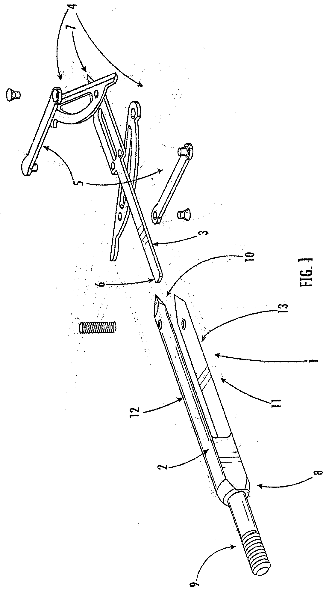
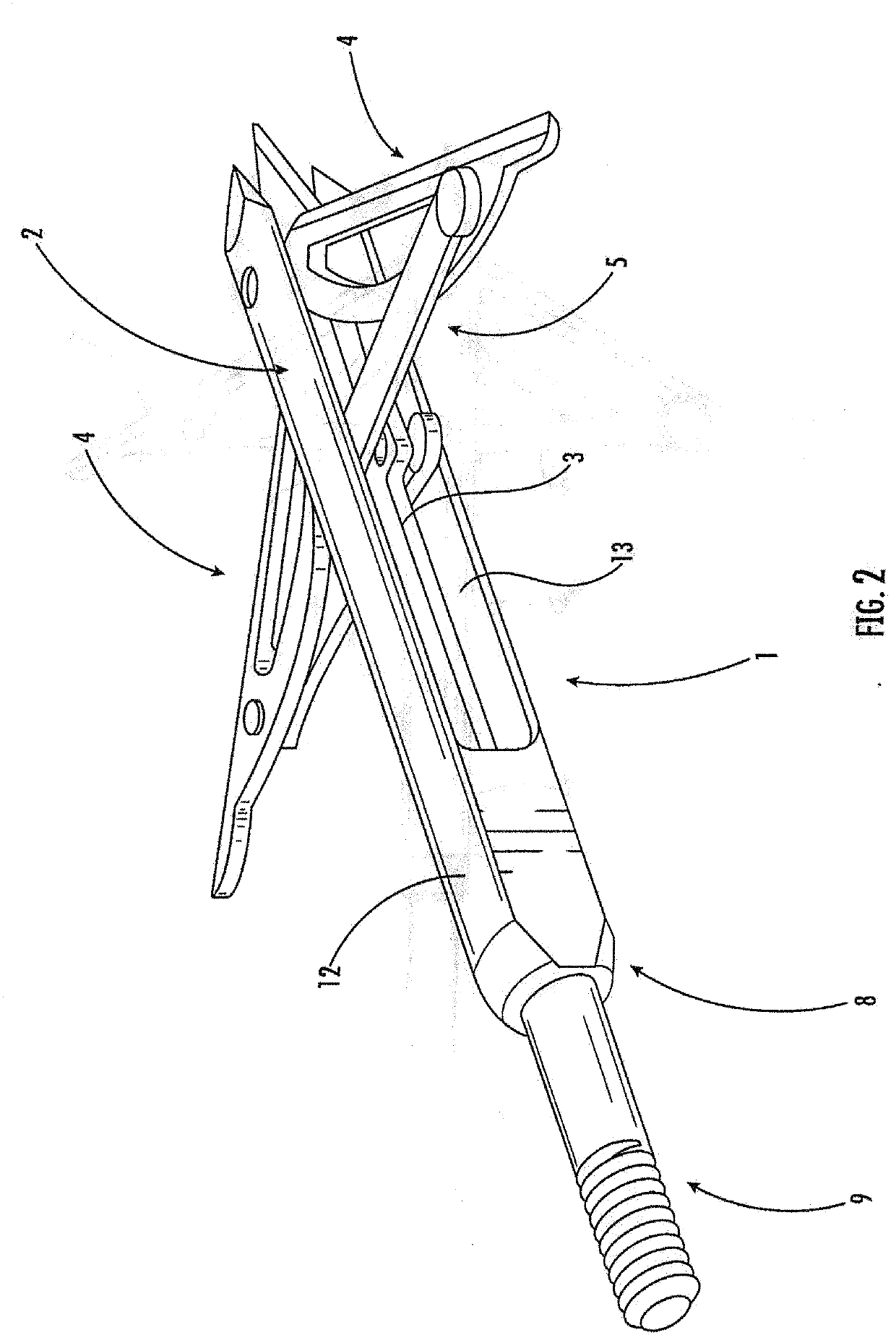
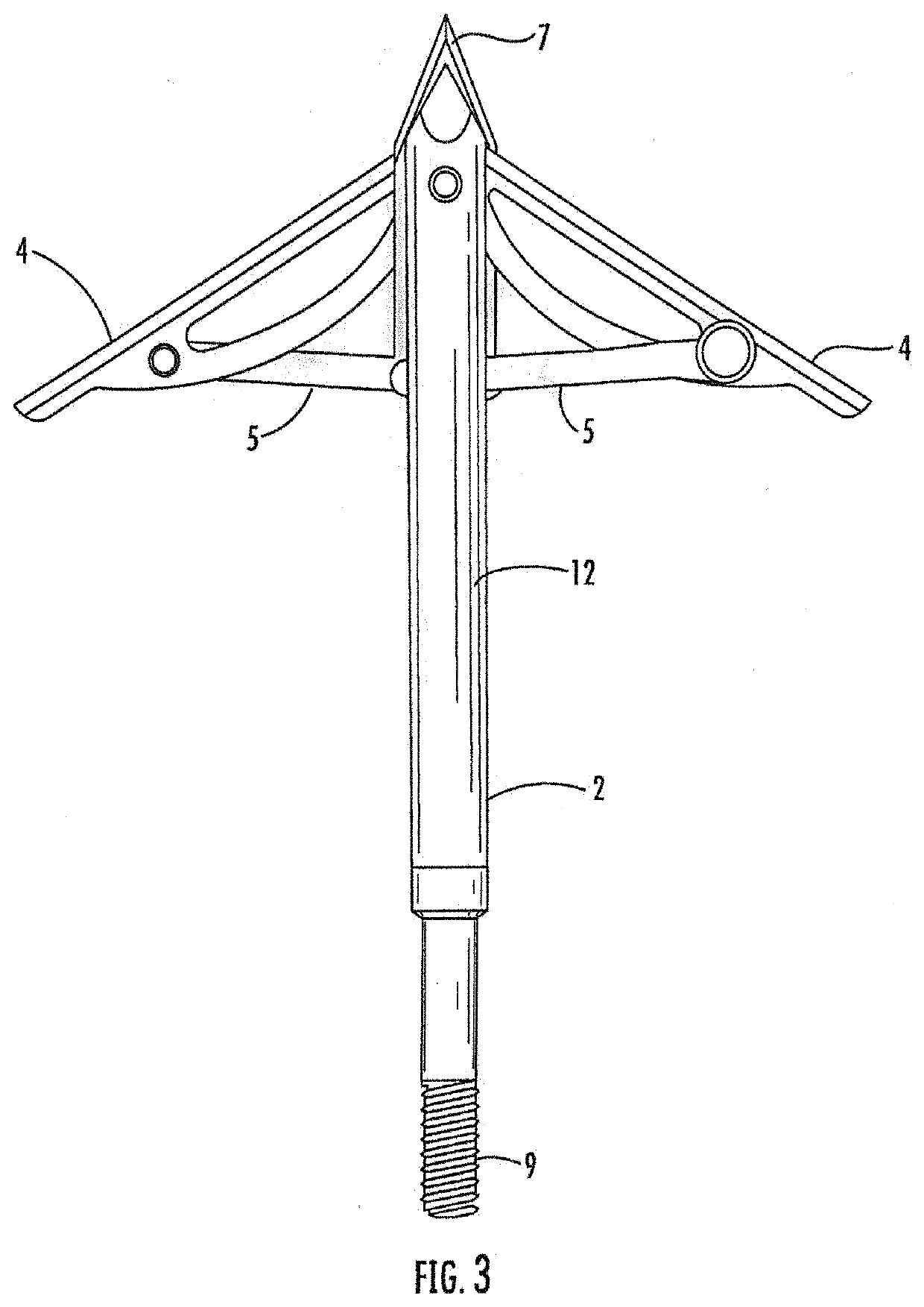
[0052]A first embodiment of the present invention is shown in detail in FIGS. 1-4. FIG. 1 shows an exploded plan view of an embodiment of the broadhead of the present invention in a deployed position. In this nonlimiting example, the body 1 comprises an outer housing 2. An inner spine 3 is arranged to be position inside the outer housing 2. At least two blades 4 are positioned to be pivotally attached to the inner spine 3. The inner spine has a first end 5 which acts a plunger end. The inner spine has a second end 6 which is pointed. The...


PUM


Abstract

The present invention is a rear-deploying broadhead with a body that is attachable to an arrow shaft. It has a body attachable to an arrow shaft by any manner known in the art, and has an outer housing, an inner spine, and at least two blades pivotally attached to the inner spine, with the inner spine having a first end with a plunger end, and a second end which is pointed. The outer housing has a first closed end that terminates proximal to a structure for attaching the body to an arrow shaft and a second end which is open. The outer housing may also have two lateral sides with are substantially open adjacent the second end of the outer housing, and the outer housing may further have a front side and a rear side which both terminate at the second end of the outer housing with a pointed end. The inner spine is shorter than the outer housing and substantially disposed in the center of the outer housing, with the plunger end seated snuggly but movably inside the outer housing adjacent the first end of the outer housing. In a nondeployed state, the second end of the inner spine extends slightly beyond the furthest extent of the second end of the outer housing. The two blades pivotally attached to the inner spine are in a retracted position in a nondeployed state, and held in a retracted position by friction, and are configured to deploy through the substantially open lateral sides of the outer housing upon movement of the inner spine toward the first end of the outer housing. The broadhead has an external coating of latex or similar material having an impact value allowing said coating to retain until the broadhead impacts a target, at which point the blades deploy through the external coating.

Description

CROSS-REFERENCE TO RELATED APPLICATIONS[0001]This application is a continuation-in-part application of U.S. patent application Ser. No. 16 / 298,133, filed Mar. 11, 2019, which claims the benefit under 35 USC 119(e) to U.S. Provisional Application No. 62 / 641604, filed Mar. 12, 2018.STATEMENT REGARDING FEDERALLY SPONSORED RESEARCH OR DEVELOPMENT[0002]Not ApplicableREFERENCE TO SEQUENCE LISTING, A TABLE, OR A COMPUTER PROGRAM LISTING COMPACT DISK APPENDIX[0003]Not ApplicableBACKGROUND OF THE INVENTION1. Field of the Invention[0004]The present invention relates to the field of archery. More particularly, the present invention is directed to a broadhead hunting arrow in which the cutting blades are deployed from the rear position of the broadhead upon impact with the target. The deployment is affected by a piston or plunger mechanism which is disposed within the body of the broadhead. The blades of the broadhead are retracted toward the body of the broadhead and may be retained in recesse...

Claims


Application Information

Patent Timeline
Patent Type & Authority Applications(United States)
IPC IPC(8): F42B6/08F42B12/34
CPCF42B6/08F42B12/34
Inventor MOTZ, TROY ALLEN
Owner MOTZ TROY ALLEN
Why Eureka
Try Eureka