Electronic enclosure with neutron shield for nuclear in-core applications

a technology of in-core applications and enclosures, applied in the field of enclosures for use, can solve the problems of long-term stability and drift of operating parameters, damage to sensors, damage cascades of permanent voids, etc., and achieve the effects of stabilizing the performance of sensors, slowing down the long-term degradation of components, and reducing the risk of damag

Active Publication Date: 2022-08-23
WESTINGHOUSE ELECTRIC CORP
View PDF9 Cites 0 Cited by
  • Summary
  • Abstract
  • Description
  • Claims
  • Application Information

AI Technical Summary

Benefits of technology

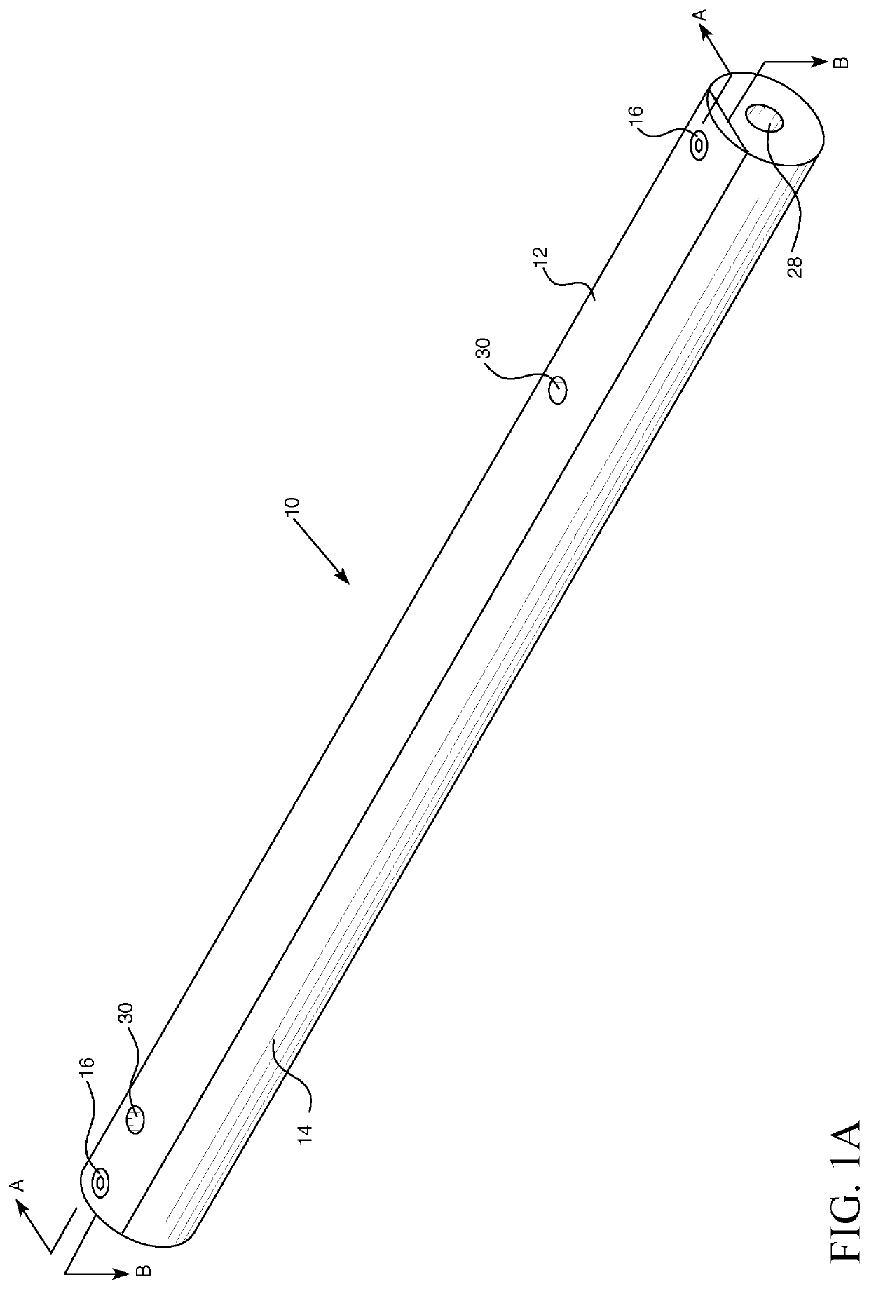
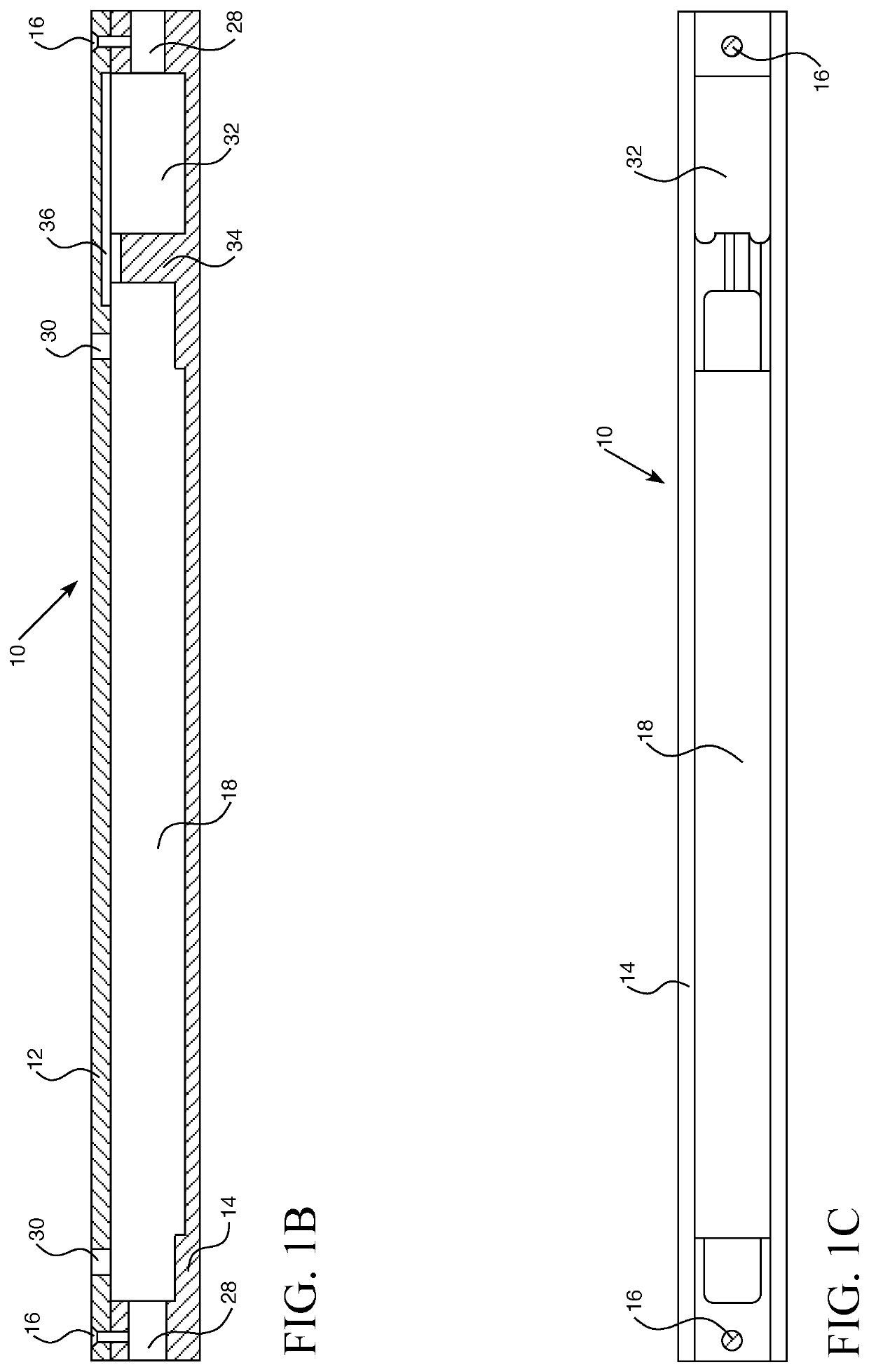
[0006]The damaging effects of neutron exposure described above can be significantly delayed or reduced, if not avoided entirely, by enclosing the non-organic components of sensors necessary to the operation and monitoring of a nuclear reactor within an electronic enclosure equipped with a neutron shield as described herein. Having such a neutron shield will stabilize the performance of the sensors and slow down the long term degradation of the components due to neutron interactions. For optimum function, in various aspects, the enclosure would reside within the inner diameter of a typical nuclear fuel rod. In various aspects, the enclosure would be able to withstand neutron flux levels typically seen in the core of a commercial PWR reactor. In various aspects, the enclosure should withstand temperatures greater than 350° C.
[0007]An electronics enclosure having neutron shielding properties according to any of the embodiments described herein will enable real time data recovery during testing of new fuel and cladding designs and in actual operation of nuclear reactors. In various aspects, the electronics enclosure with neutron shielding properties described herein may isolate the electronic components from electrically conductive fuel rods. In various aspects, the electronics enclosure with neutron shielding properties described herein may provide the opportunity to shield non-organic electronics from neutrons and extend the time required to reach a target fluence.

Problems solved by technology

Tests have shown that some electronic sensors, such as non-organic capacitors, inductors, and surge arrestor gas discharge tubes, will operate at conditions equivalent to the elevated temperatures and radiation environments found in pressurized water reactors (PWR), but that the long term stability and drift of their operating parameters degrade over time.
Over time, the radiation will interact with the materials in the electronic components of the sensors to impact performance and in many cases cause damage to the sensors.
The effect of neutron exposure produces damage cascades of permanent voids and interstitials within the material and in some cases cause transmutation reactions to occur.

Method used


Image

  • Electronic enclosure with neutron shield for nuclear in-core applications
  • Electronic enclosure with neutron shield for nuclear in-core applications
  • Electronic enclosure with neutron shield for nuclear in-core applications

Examples


Embodiment Construction

[0024]As used herein, the singular form of “a”, “an”, and “the” include the plural references unless the context clearly dictates otherwise. Thus, the articles “a” and “an” are used herein to refer to one or to more than one (i.e., to at least one) of the grammatical object of the article. By way of example, “an element” means one element or more than one element.

[0025]Directional phrases used herein, such as, for example and without limitation, top, bottom, left, right, lower, upper, front, back, and variations thereof, shall relate to the orientation of the elements shown in the accompanying drawing and are not limiting upon the claims unless otherwise expressly stated.

[0026]In the present application, including the claims, other than where otherwise indicated, all numbers expressing quantities, values or characteristics are to be understood as being modified in all instances by the term “about.” Thus, numbers may be read as if preceded by the word “about” even though the term “ab...


PUM


Abstract

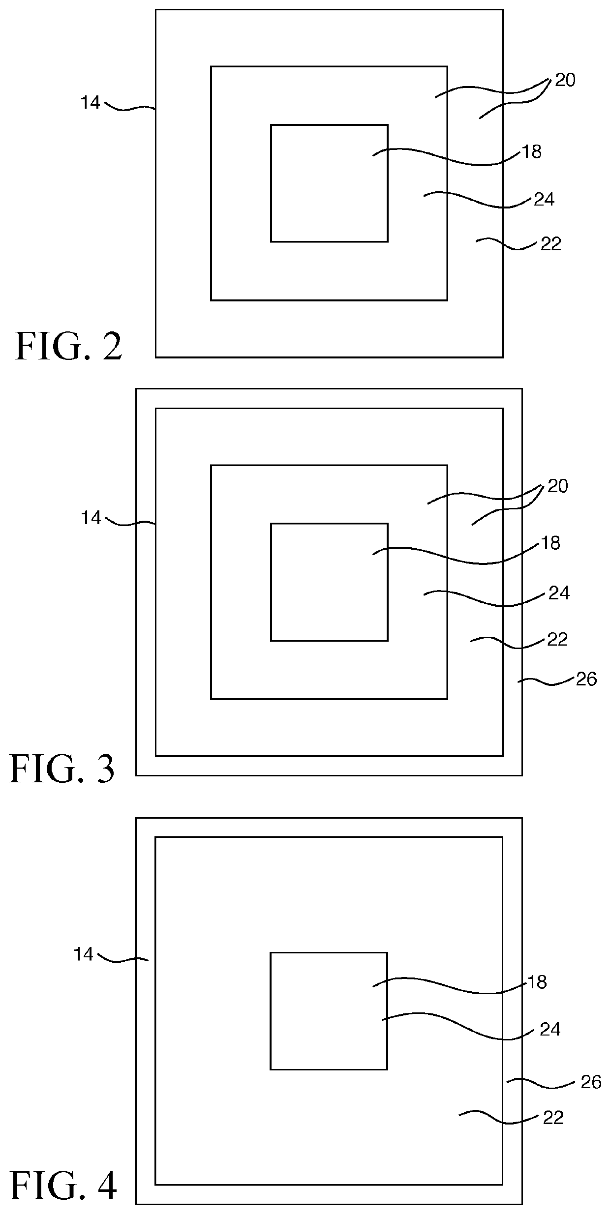
An enclosure for non-organic electronic components is provided which includes an inner cavity for housing non-organic electronic components and a neutron shielding barrier surrounding the inner cavity and the electronic components housed within the cavity. The barrier is formed from a neutron reflecting material in solid or powdered form and a neutron absorbing material in solid or powdered form. An optional structural support is provided in certain aspects of the enclosure design.

Description

BACKGROUND OF THE INVENTION1. Field of the Invention[0001]The invention relates to enclosures for use in nuclear fuel rods to shield in-core electronic components.2. Description of the Prior Art[0002]Sensors are placed in and around nuclear reactors to monitor conditions within the reactor. Tests have shown that some electronic sensors, such as non-organic capacitors, inductors, and surge arrestor gas discharge tubes, will operate at conditions equivalent to the elevated temperatures and radiation environments found in pressurized water reactors (PWR), but that the long term stability and drift of their operating parameters degrade over time. For example, a capacitor's capacitance, an inductor's inductance, or a gas discharge tube's break down voltage will degrade under the conditions present in nuclear reactors.[0003]The sensors placed in reactors are exposed to ionizing radiation from both neutrons and gamma radiation. Over time, the radiation will interact with the materials in t...

Claims


Application Information

Patent Timeline
Patent Type & Authority Patents(United States)
IPC IPC(8): G21F3/00G21F1/00G21F1/08G21F1/12G21C17/10G21C3/18G21C3/20
CPCG21F3/00G21F1/00G21F1/08G21F1/12G21F1/125G21C3/18G21C3/20G21C17/102G21C3/16G21C3/10
Inventor ARNDT, JEFFREY L.CARVAJAL, JORGE V.STAFFORD, SHAWN C.HEAGY, MELISSA M.ABEL, II, JOHN R.FLAMMANG, ROBERT W.ICKES, MICHAEL R.
Owner WESTINGHOUSE ELECTRIC CORP
Why Eureka
Try Eureka