Impeller shaft to bearing interface for centrifugal blood pump

a centrifugal pump and bearing technology, applied in the field of centrifugal pumps, can solve the problems of increasing the probability of hemolysis (damage to blood corpuscles), and achieve the effect of preventing hemolysis from being formed

Active Publication Date: 2018-12-04
TERUMO KK
View PDF14 Cites 3 Cited by
  • Summary
  • Abstract
  • Description
  • Claims
  • Application Information

AI Technical Summary

Benefits of technology

[0006]The present invention has been made in consideration of the foregoing problems, and an object thereof is to provide a centrifugal pump which can prevent hemolysis from being formed due to sliding between a shaft and a pivot bearing.
[0008]According to the configuration of the present invention, a relationship between the radius of curvature of the shaft end of the shaft and the radius of curvature of the bearing surface of the bearing is set within the above-referenced range. Therefore, a gap between the shaft end of the shaft and the bearing surface of the bearing becomes suitable in size. Accordingly, it is possible to further reduce hemolysis from occurring due to sliding between the shaft and the bearing.
[0009]In the centrifugal pump of the invention, in at least one of the bearings disposed at opposite axial ends of the shaft, the radius of curvature of the shaft end ranges from 1.25 mm to 1.5 mm, and the radius of curvature of the bearing surface ranges from 1.5 mm to 2.5 mm. According to this configuration, it is possible to more effectively prevent hemolysis from occurring on a sliding surface between the shaft and the bearing.
[0010]In the centrifugal pump, in at least one of the bearings disposed at opposite axial ends of the shaft, the radius of curvature of the shaft end is about 1.5 mm, and a radius of curvature of the bearing is about 2.0 mm. According to this configuration, it is possible to more effectively prevent hemolysis from occurring on the sliding surface between the shaft and the bearing.
[0011]In the centrifugal pump, a bearing preload with respect to the shaft in the axial direction may range from about 30 N to about 60 N. According to this configuration, together with the hemolysis prevention effect achieved by setting the radius of curvature as described above, it is possible to more effectively prevent hemolysis from being formed, and it is also possible to prevent a thrombus from being formed and to avoid damage to a bonded portion (e.g., occurrence of a crack, and the like) between a base of the housing and a cover.
[0013]According to the centrifugal pump of the present invention, it is possible to prevent hemolysis from being formed due to sliding between the shaft and the pivot bearing.

Problems solved by technology

In a case of the centrifugal pumps employing the pivot bearing, however, the occurrence of hemolysis (damage to blood corpuscles) may become more likely due to sliding between the shaft and the pivot bearing.

Method used


Image

  • Impeller shaft to bearing interface for centrifugal blood pump
  • Impeller shaft to bearing interface for centrifugal blood pump
  • Impeller shaft to bearing interface for centrifugal blood pump

Examples


Embodiment Construction

[0021]Hereinafter, description will be given regarding a favorable embodiment of a centrifugal pump of the present invention, with reference to the accompanying drawings.

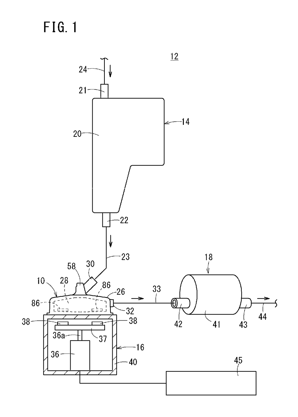
[0022]FIG. 1 is a schematic view of a heart-lung machine 12 including a centrifugal pump 10 of the present invention. For example, the heart-lung machine 12 is used for cardiac surgery or the like. The heart-lung machine 12 performs oxygenation of blood drained from a patient, filtering for elimination of foreign bodies, and the like, then returning the blood to the patient. As illustrated in FIG. 1, the heart-lung machine 12 includes a reservoir 14, a centrifugal pump 10, a pump driving unit 16, and a gas exchange unit 18.

[0023]The reservoir 14 temporarily stores blood removed from a patient (venous blood). The reservoir 14 has a reservoir main body 20, a blood inlet port 21 which is provided in an upper portion of the reservoir main body 20 and is connected to a venous line 24 for delivering blood from a blood dra...


PUM


Abstract

A centrifugal pump (10) includes a housing (26), an impeller (28) that is rotatably disposed inside the housing (26), a shaft (62) that has spherical surface-shaped shaft ends (66) at both ends in an axial direction, and bearings (70) that have spherical surface-shaped bearing surfaces (73) respectively and pivotally supporting the shaft ends (66). In at least one of the bearings (70) disposed on both sides of the shaft (62) in the axial direction, a ratio of a radius of curvature of the shaft end (66) with respect to a radius of curvature of the bearing surface (73) of the bearing (70) is equal to or less than 85%.

Description

CROSS REFERENCE TO RELATED APPLICATIONS[0001]This application is a continuation of PCT Application No. PCT / JP2014 / 083611, filed Dec. 18, 2014, based on and claiming priority to Japanese application no. 2013-272857, filed Dec. 27, 2013, both of which are incorporated herein by reference in their entirety.TECHNICAL FIELD[0002]The present invention relates to a centrifugal pump which delivers liquid such as blood and the like.BACKGROUND ART[0003]During cardiac surgery, a heart-lung machine is utilized. The heart-lung machine is used by being embedded in an extracorporeal circulation circuit and performs oxygenation of blood drained from a patient, and filtering for elimination of foreign bodies, and the like. There are various types of heart-lung machines (also known as perfusion systems) depending on differences such as the type of gas exchange unit, the type of pump, the position arrangement of pump, and the like. However, a heart-lung machine generally includes a reservoir (for veno...

Claims


Application Information

Patent Timeline
Patent Type & Authority Patents(United States)
IPC IPC(8): F04D29/041F16C17/08F04D13/02F04D1/00F04D29/22A61M1/36A61M1/10A61M60/113A61M60/232A61M60/38A61M60/804A61M60/825
CPCF04D13/026A61M1/1013A61M1/3666F04D1/00F04D29/041F04D29/2255F16C17/08F04D29/0413F16C2360/44A61M1/101A61M1/1006F16C2240/70F04D29/0467A61M60/113A61M60/419A61M60/38A61M60/232A61M60/804A61M60/825A61M1/3623
Inventor KUMANO, KOKO
Owner TERUMO KK
Why Eureka
Try Eureka