Sliding friction-free gear

a friction-free gear and sliding technology, applied in the field of gears, can solve the problems of reducing durability and efficiency, complicated and expensive, and affecting the reliability of the gear,

Active Publication Date: 2018-12-04
OLEDZKI WIESLAW JULIAN
View PDF8 Cites 0 Cited by
  • Summary
  • Abstract
  • Description
  • Claims
  • Application Information

AI Technical Summary

Benefits of technology

[0005]Thus the principal objective of the present invention is to provide a gear that outperforms known power transmitting devices particularly in aspects of compactness, lightness, reliability, insusceptibility to seizure, and transmission capacity, thus being capable of meeting most stringent requirements of aviation industry.
[0006]Another objective of the present invention is to provide a one stage gear of compact structure having large transmission ratio (16:1 to 50:1 and more).
[0007]These and other objectives are achieved according to the present invention by providing sliding friction-free gears, the cooperating members of which contact along a line like in conventional evolvent gears, and unlike Wildhaber-Novikov's gear (where the momentary contact between teeth of cooperating toothed wheels is pointwise), which therefore offer much larger transmission capacity and are much less prone to seizure than known gears.
[0008]The method for achieving sliding friction-free gears according to the present invention consists in providing gears with a specific toothing (or rather cams of specific profiles, as described below and claimed in separate patent claims), and separating cooperating gears by rollers that roll over the cams of the gears, thus eliminating the sliding friction between the gears. The rollers are mounted rotatably e.g. in sliders or eccentrics, wherein the sliders, resp. eccentrics, are mounted slidingly, resp. rotatably, in a yoke. The rollers are free to execute oscillating motion relative the yoke while rolling over the cam profiles of the cams of the gears.
[0009]As mentioned above, thanks to the virtual absence of the sliding friction between the transmission elements meeting along the lines, the gear of the present invention features substantially greater transmission capacity than ordinary gears of the same dimensions. Thus the gear according to the present invention is expected to offer substantial gains in transmission's capacity / weight and transmission's capacity / size ratios and transmission's reliability (e.g. ability to work properly in the absence of lubrication) in comparison with conventional gears.
[0010]An interesting and important advantage of the gear according to the present invention is that the rollers separating cams remain in constant contact with cams, which contributes to the gear reliability and durability; moreover the rollers do the job of bearing, which renders separate bearings supporting output shaft unnecessary.

Problems solved by technology

All these drives have important disadvantages.
Thus friction drives that depend upon friction force acting between moving parts in contact to transmit motion have very limited transmission capacity and therefore are usually bulky and heavy, and suffer from slippage between cooperating members which diminishes their durability and efficiency, and renders their reliability questionable.
Hydraulic transmissions are capable of coping with large loads while retaining compact size, but are complicated and expensive, and feature poor efficiency and not always satisfactory reliability.
Electric transmissions are complicated, heavy and expensive, and definitely not suitable for application in high power drive lines of aerial vehicles.
However also gears have some disadvantages: Cooperating gear teeth slide against each other (rarely used Wildhaber-Novikov's meshing being an exception), which diminishes gear's transmission capacity and reliability, and causes gears require good lubrication, as lack of lubrication leads to seizure and catastrophic failure.

Method used


Image

  • Sliding friction-free gear
  • Sliding friction-free gear
  • Sliding friction-free gear

Examples


first embodiment

, Variant a (FIGS. 1-15)

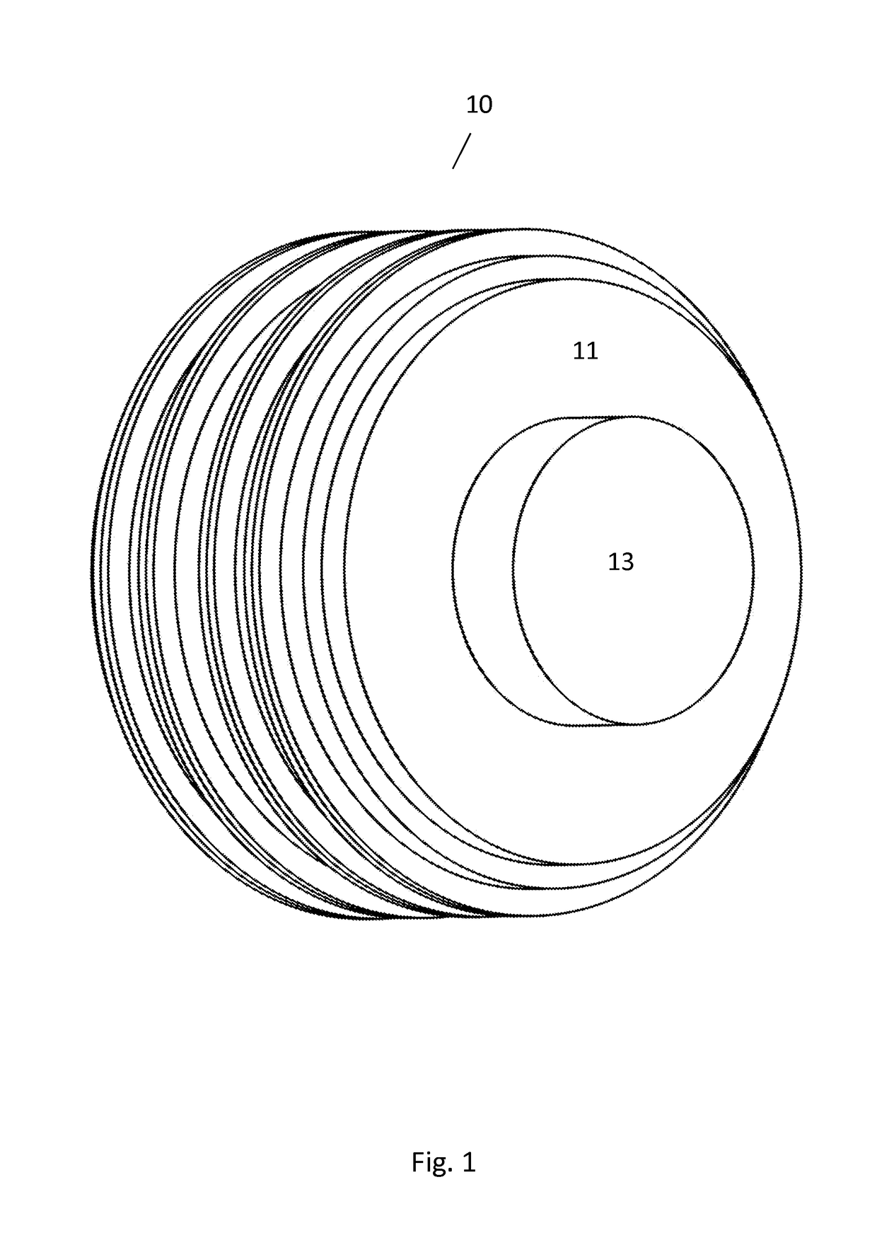
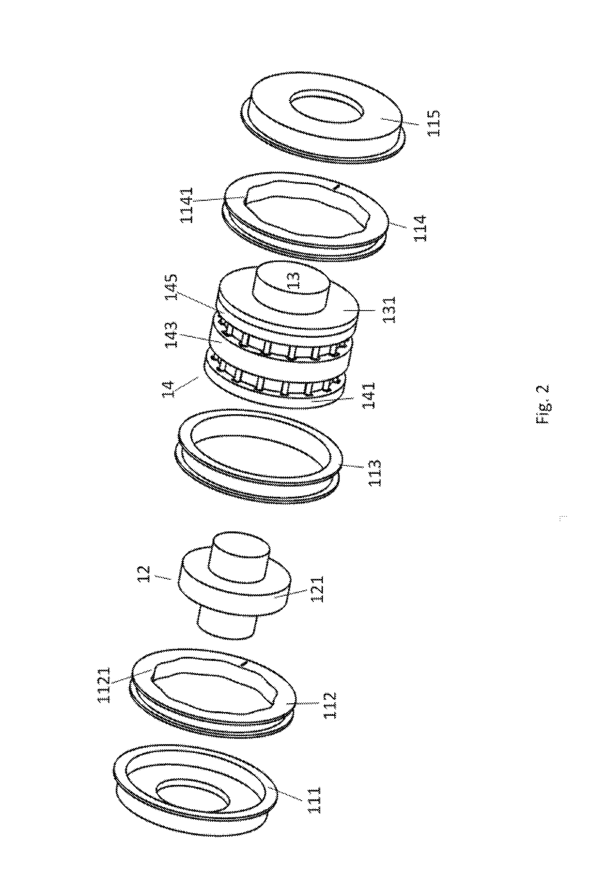
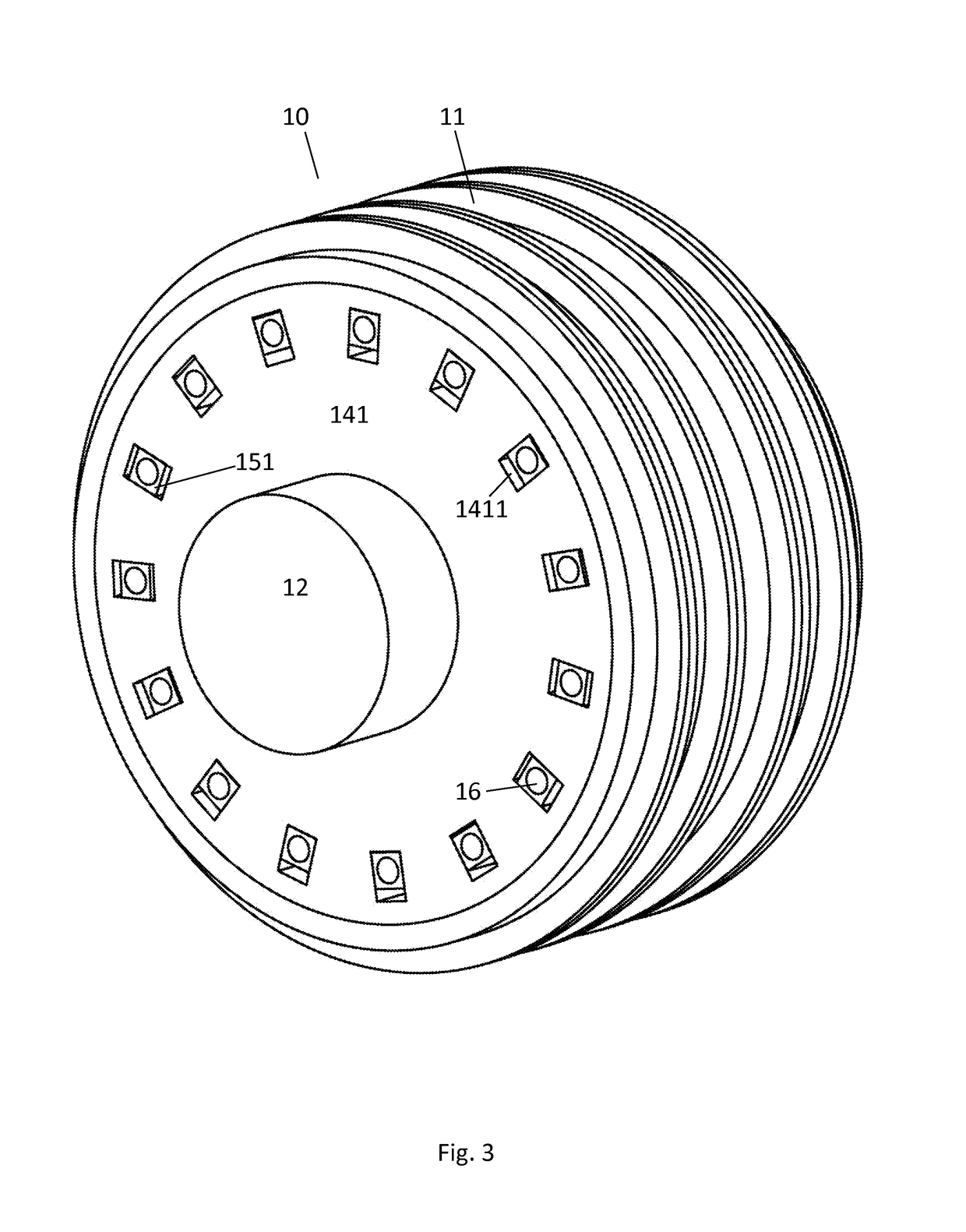
[0086]A gear 10 according to the present invention, being the first preferred embodiment of the invention (see FIGS. 1-17, and particularly FIGS. 1-15), has a body 11, an input shaft 12, an output shaft 13, and a roller's yoke 14 (FIGS. 1, 2). Body 11 is composed of five parts 111, 112, 113, 114, and 115 joined by screws (not shown) or in any other suitable manner (FIGS. 1, 2, 3, 4, 7, 8). Input shaft 12 is supported pivotally in body part 111; output shaft 13 is supported pivotally in body part 115, coaxially with the input shaft 12 (FIGS. 2, 7, 8). Output shaft 13 has a disc 131 fastened thereon (FIGS. 2, 7, 11). Roller's yoke 14 is fastened with the help of screws (not shown), or in any other suitable manner, to the disc 113. Roller's yoke 14 is composed of two principal elements 141, and 145, and three intermediate elements 142, 143, 144, connected together by screws (not shown), or in any other suitable manner (FIGS. 7, 8, and particularly FIGS. 11, 12, ...

second embodiment (figs.18-23)

Second Embodiment (FIGS. 18-23)

[0092]The second embodiment of the gear according to the present invention differs from the first embodiment by the method of connecting the rollers with output shaft 13. This circumstance forces other profiles of cams, but renders the roller's yoke unnecessary.

[0093]Gear 10 being the second embodiment of the present invention (FIGS. 18-23) has a body 11, input shaft 12, output shaft 13, and a plurality (in this example 9) of roller assemblies 161-162-17-18-19. Body 11 (FIGS. 18-20 and 22) is composed of four parts 111, 112, 113, and 114. Placed in part 112 of body 11 there is cam 1121 with a number (10 in this example) of lobes; thus the number of lobes is greater by one than the number of roller assemblies, so output shaft 13 and input shaft 12 rotate in mutually opposite directions, and the transmission ratio of the gear equals −n, where n is the number of roller assemblies (thus in this example the transmission ratio equals −9). Input shaft 12 is m...

third embodiment (figs.24-33)

Third Embodiment (FIGS. 24-33)

[0096]The third preferred embodiment of the gear according to the instant invention differs from the first and the second embodiment in that cam 1121 placed in body 11 of the first and second embodiment is replaced by cam 132 placed on output shaft; this difference also forces a change in the method of mounting of roller assemblies, which in the present example are “stationary”, i.e. mounted directly in the gear body 11.

[0097]Thus gear 10 being the third embodiment of the invention has body 11, input shaft 12, output shaft 13, and a number n (in this example 9) of roller assemblies 21-22-23-161-162-163 (FIGS. 24-30). Input 12 and output 13 shafts are mounted pivotally and coaxially in body 11. Arranged in body 11 there are n sockets 116, in which semi-circular levers 23 of roller assemblies 21-22-23-161-162-163 are mounted pivotally (FIGS. 24-29, and particularly FIG. 28). Input shaft has cam (in this example an eccentric) 121 placed thereon. Output sha...


PUM


Abstract

A sliding friction-free gear has cams of specific profiles, rollers separating cooperating cams that roll over the cams of the gears, thus eliminating the sliding friction between the gears. The rollers are mounted rotatably e.g. in sliders or eccentrics, wherein the sliders, resp. eccentrics, are mounted slidingly, resp. rotatably, in a yoke attached rigidly to a shaft. The rollers are free to execute oscillating motion relative the yoke while rolling over the cam profiles of the cams of the gears. The cooperating members of the gear contact along a line like in conventional evolvent gears, and unlike in the Wildhaber-Novikov's gear (where the momentary contact between teeth of cooperating toothed wheels is pointwise); therefore the gear according to the present invention offers much larger transmission capacity and is much less prone to seizure than known gears.

Description

TECHNICAL FIELD OF THE INVENTION[0001]The invention relates to gears, and is particularly concerned with a method for elimination of sliding friction between cooperating gear members.STATE OF THE ART AND BACKGROUND OF THE INVENTION[0002]Power transmitting devices known in the prior art are naturally divided into the following four categories: friction drives, hydraulic (hydrostatic or hydrodynamic) transmissions, electric transmissions, and cogwheels or gears. All these drives have important disadvantages. Thus friction drives that depend upon friction force acting between moving parts in contact to transmit motion have very limited transmission capacity and therefore are usually bulky and heavy, and suffer from slippage between cooperating members which diminishes their durability and efficiency, and renders their reliability questionable. Hydraulic transmissions are capable of coping with large loads while retaining compact size, but are complicated and expensive, and feature poor...

Claims


Application Information

Patent Timeline
Patent Type & Authority Patents(United States)
IPC IPC(8): F16H15/52
CPCF16H15/52F16H25/06
Inventor OLEDZKI, WIESLAW JULIAN
Owner OLEDZKI WIESLAW JULIAN
Why Eureka
Try Eureka