Method and system for motion adaptive fusion of optical images and depth maps acquired by cameras and depth sensors

a technology of depth maps and optical images, applied in image enhancement, distance measurement, instruments, etc., can solve the problems of significant quality degradation and significant depth change between frames, and achieve the effect of improving the resolution of depth images and the spatial resolution of depth sensors

Active Publication Date: 2018-12-04
MITSUBISHI ELECTRIC RES LAB INC
View PDF12 Cites 0 Cited by
  • Summary
  • Abstract
  • Description
  • Claims
  • Application Information

AI Technical Summary

Benefits of technology

[0010]The spatial resolution of depth sensors is often significantly lower compared to that of conventional optical cameras. The embodiments of the invention improve the resolution of depth images using higher resolution optical intensity images as side information. More specifically, the embodiments fuse sensor measurement output by low-resolution depth sensors and high-resolution optical cameras.
[0011]Incorporating temporal information in videos can significantly improve the results. In particular, the embodiments improve depth resolution, exploiting space-time redundant features in the depth and intensity images using motion-adaptive low-rank regularization. Results confirm that the embodiments can substantially improve the quality of the estimated high-resolution depth image. This approach can be a first component in methods and systems using vision techniques that rely on high resolution depth information.

Problems solved by technology

One challenge is determining this information in the presence of scene, camera, and object motion between multiple temporally adjacent frames.
Another challenge in incorporating time into depth estimation is that depths can change significantly between frames.
This results in abrupt variations in depth values along the temporal dimension and can lead to significant degradation in the quality of the result.

Method used


Image

  • Method and system for motion adaptive fusion of optical images and depth maps acquired by cameras and depth sensors
  • Method and system for motion adaptive fusion of optical images and depth maps acquired by cameras and depth sensors
  • Method and system for motion adaptive fusion of optical images and depth maps acquired by cameras and depth sensors

Examples


Embodiment Construction

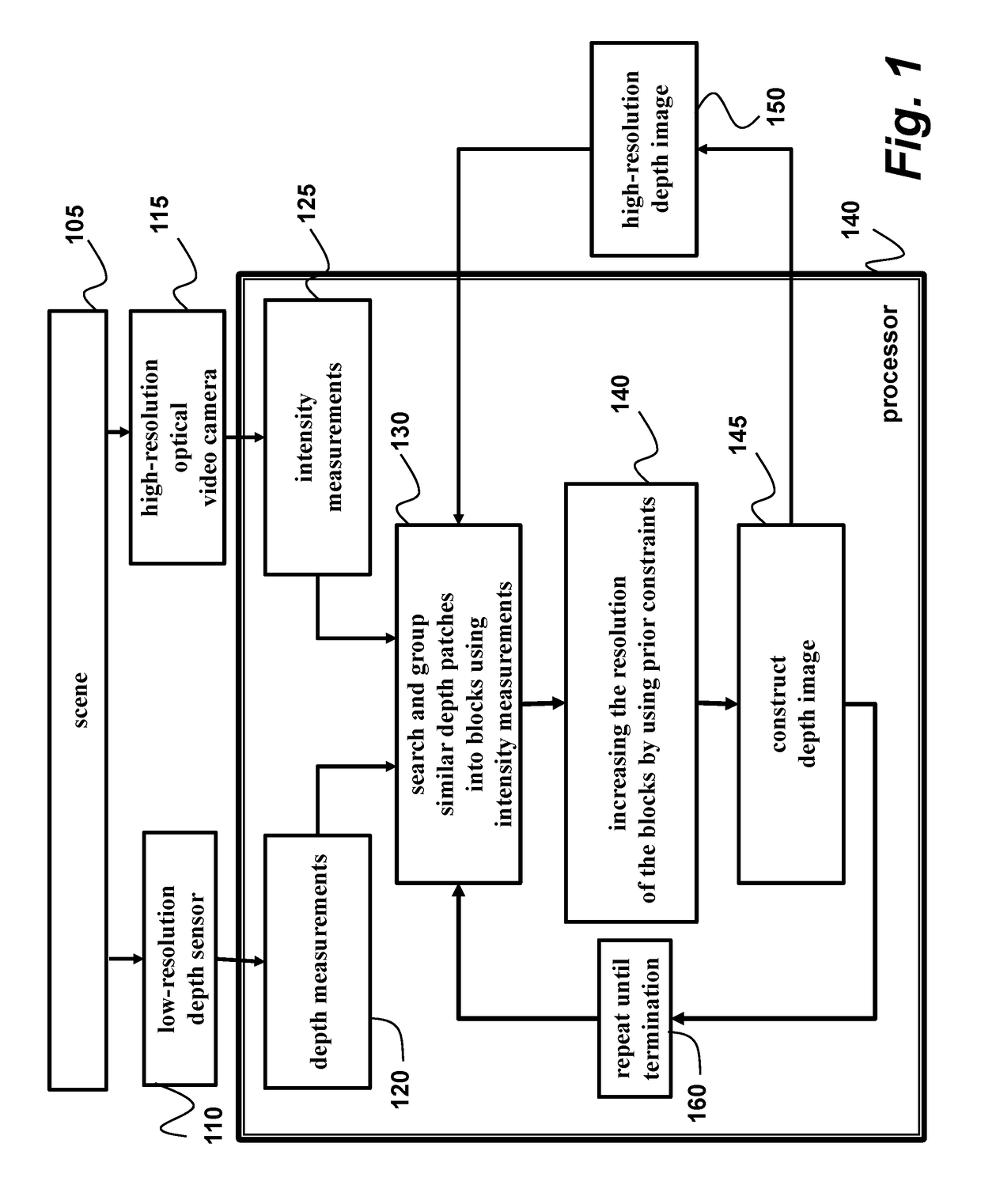
[0018]As shown in FIG. 1, the embodiments of our invention fuse measurement output by low-resolution depth sensors and a high-resolution optical cameras to improve the resolution of a depth image.

[0019]The embodiments construct a high-resolution depth image by minimizing a cost function that combines a data-fidelity term and a regularizer. Specifically, we impose a quadratic data fidelity term that controls the error between the measured and estimated depth values. The regularizer groups similar depth patches from multiple frames and penalizes the rank of the resulting depth image.

[0020]Because we use patches from multiple frames, our method is implicitly motion adaptive. Thus, by effectively combining measurements from multiple views of the scene, depth estimates are improved.

[0021]Method and System Overview

[0022]Depth measurements 120 are acquired of a scene 105 with a depth sensor 110, e.g., the depth sensor can be a light radar (LIDAR) sensor. In addition, intensity measurements...


PUM


Abstract

A method and system for fusing sensed measurements includes a depth sensor to acquire depth measurements of a scene as a sequence of frames, and a camera configured to acquire intensity measurements of the scene as a sequence of images, wherein a resolution of the depth sensor is less than a resolution of the camera. A processor searches for similar patches in multiple temporally adjacent frames of the depth measurements, groups the similar patches into blocks using the intensity measurements, increases a resolution of the blocks using prior constraints to obtain increased resolution blocks, and then constructs a depth image with a resolution greater than the resolution of sensor from the increased resolution blocks.

Description

FIELD OF THE INVENTION[0001]This invention relates to sensing systems and methods, and more specifically to fusing sensed measurements output by low-resolution depth sensors and a high-resolution optical cameras.BACKGROUND OF THE INVENTION[0002]One of the important challenges in computer vision applications is acquiring high resolution depth maps of scenes. A number of common tasks, such as object reconstruction, robotic navigation, and automotive driver assistance can be significantly improved by complementing intensity data from optical cameras with high resolution depth maps. However, with current sensor technology, direct acquisition of high-resolution depth maps is very expensive.[0003]The cost and limited availability of such sensors imposes significant constraints on the capabilities of computer vision systems and hinders the adoption of methods that rely on high-resolution depth maps. Thus, a number of methods provide numerical alternatives to increase the spatial resolution...

Claims


Application Information

Patent Timeline
Patent Type & Authority Patents(United States)
IPC IPC(8): H04N5/232G06T7/00G06K9/62G01S17/08G01C3/08G06T3/40
CPCG06T7/50G06T7/11H04N5/23232G01C3/08G06K9/6215G06K9/6267G06T3/4053G01S17/08G06T2207/20021G06F18/22G06F18/24H04N23/951
Inventor KAMILOV, ULUGBEKBOUFOUNOS, PETROS T
Owner MITSUBISHI ELECTRIC RES LAB INC
Why Eureka
Try Eureka