Inserter for an intrauterine system

a technology of intrauterine system and inserter, which is applied in the direction of obstetrical instruments, contraceptives, female contraceptives, etc., can solve the problems of difficult to make the ius stop in the correct position, end enter almost completely, and the wing remains too wide, so as to minimise the possibility of the ius being stuck in the insertion tube, the relative movement of the insertion tube can be shorter, and the effect of convenient us

Active Publication Date: 2018-12-11
BAYER OY
View PDF25 Cites 7 Cited by
  • Summary
  • Abstract
  • Description
  • Claims
  • Application Information

AI Technical Summary

Benefits of technology

[0011]An object of the invention is to provide a simple, easy to use inserter for the positioning of an intrauterine system in the uterus and a kit comprising an intrauterine system and said inserter. An object of the invention is particularly to provide an inserter and a kit with which, during the insertion process, no manual handling of the strings or the IUS is needed. An object of the invention is especially to provide an inserter wherein the relative movement of the insertion tube can be shorter as compared to previous inserters, as this would lead to a more accurate insertion and minimise the possibility of the IUS to be stuck in the insertion tube.

Problems solved by technology

If the IUS is pulled into the insertion tube by means of the removal string, which is usually the case with the existing devices, it is understandable that it is difficult to make the IUS stop in the correct position, especially if the relative movement of the insertion tube with respect to the plunger is not restricted by any stop member.
Pulling with too much force easily makes these ends enter almost completely into the insertion tube.
During the insertion of the device, the sharp edges of the insertion tube may interfere with the introduction of the device through the cervical canal.
The diameter at the level of the wings remains too wide, which makes the introduction of the device more difficult.
If the device is pulled in the insertion tube or onto the plunger in a wrong angle or position, the edges of the insertion tube easily damage the loop or the body of the IUS.
In the worst case the device will be stuck in the insertion tube.

Method used


Image

  • Inserter for an intrauterine system
  • Inserter for an intrauterine system
  • Inserter for an intrauterine system

Examples


Embodiment Construction

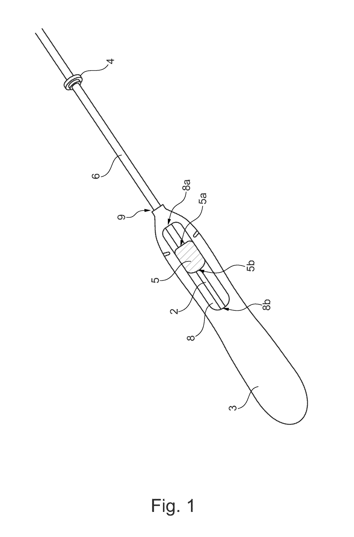
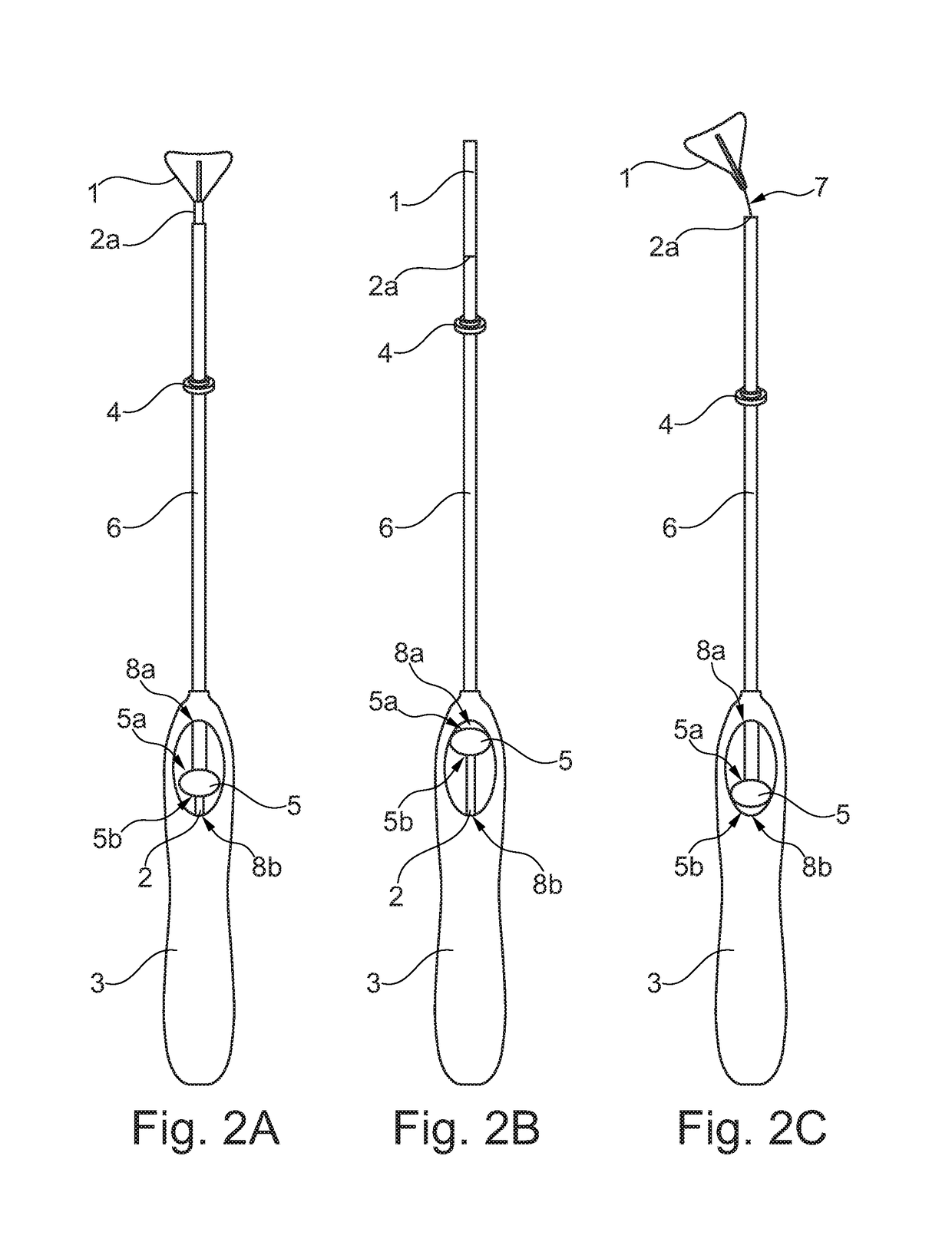
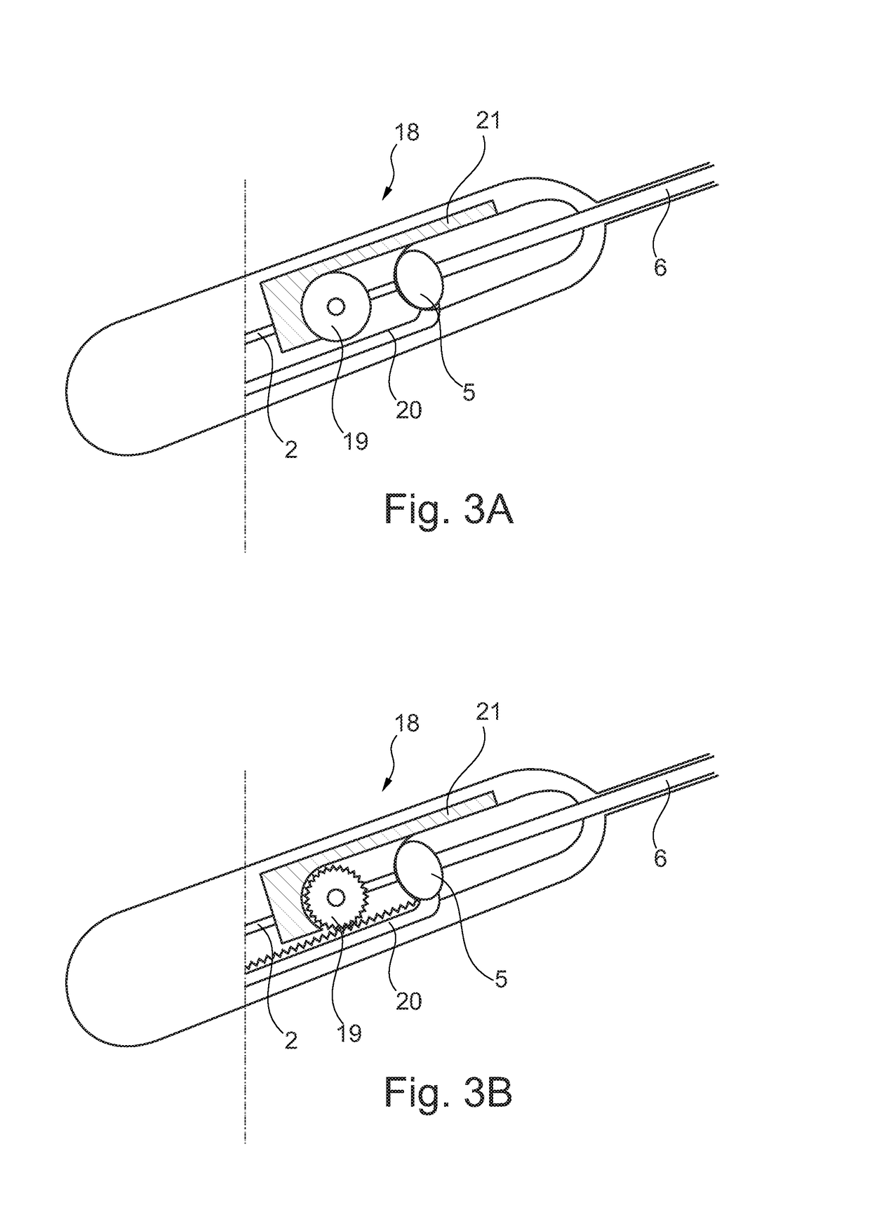
[0021]The inserter according to this invention thus comprises at least one element interconnected on at least one point to a means or member which can pivot, turn or rotate with respect to the longitudinal axis of the handle and the inserter in a way that the movement of the slider thus generates the movement of the insertion tube and the plunger at the same time but to opposite directions, via pivoting, turning or rotation of the rotation part. The movement of the slider also causes the release of the removal string or strings of the intrauterine system as soon the IUS has correctly been positioned in the uterus. Thus, with the present invention, no manual handling of the strings as such is needed, which increases accuracy and hygiene of the insertion procedure. A person skilled in the art is readily able to design such devices and some examples are given in connection with the drawing.

[0022]The rotation axis of the rotation part is perpendicular to the longitudinal axis of the ins...


PUM


Abstract

An inserter for an intrauterine system includes a handle. The handle has a longitudinal opening at its first end, the opening having a longitudinal axis parallel to the longitudinal axis of the inserter, a first end and a second end, a movable slider arranged in the longitudinal opening and having a first end and a second end. The inserter also includes a movable plunger and an insertion tube arranged around the plunger having a first end and a second end, with its second end attached to the slider. The handle further includes a lock for reversibly locking the intrauterine system in relation to the plunger via a removal string of the intrauterine system, the lock being attached to the plunger and being controllable at least by a part or an extension of the slider and / or of the insertion tube or of the handle.

Description

FIELD OF THE INVENTION[0001]The present invention relates to an inserter for an intrauterine system, comprising a handle having a longitudinal opening at its first end, said opening having a longitudinal axis parallel to the longitudinal axis of the inserter, a first end and a second end, a movable slider arranged in said longitudinal opening and having a first end and a second end, a movable plunger, an insertion tube arranged around the plunger having a first end and a second end, with its second end attached to the slider, locking means for reversibly locking the intrauterine system in relation to the plunger via a removal string of the intrauterine system, said locking means being attached to the plunger and being controllable at least by a part or an extension of the slider and / or of the insertion tube or of the handle. The invention also relates to a kit comprising an inserter.BACKGROUND OF THE INVENTION[0002]Various types of inserters have been developed for the positioning o...

Claims


Application Information

Patent Timeline
Patent Type & Authority Patents(United States)
IPC IPC(8): A61F6/18A61F6/14
CPCA61F6/18A61F6/144A61B17/42
Inventor JUTILA, ILKKALYYTIKAINEN, HEIKKI
Owner BAYER OY
Why Eureka
Try Eureka