Shower head structure

a shower head and structure technology, applied in water installations, water resource protection, construction, etc., can solve the problems of poor water-saving effect, inability to provide physical ease and relaxation, and inability to discharge water from existing shower heads, and achieve good water-saving effect and strong force of fine spouts

Active Publication Date: 2018-12-11
XIAMEN LOTA INT CO LTD
View PDF7 Cites 3 Cited by
  • Summary
  • Abstract
  • Description
  • Claims
  • Application Information

AI Technical Summary

Benefits of technology

[0004]The primary objective of the present invention is to provide a shower head structure which can increase the force of the outflow of water effectively. The water flow is bubble water for the user to feel soft and comfortable. The water won't spray about. The water-saving effect is good. The shower head of the present invention is suitable for low pressure environment.
[0015]The face panel of the present invention has a plurality of water outlet units. Each water outlet unit includes a plurality of jet orifices. The water flowing from the plurality of jet orifices forms a bunched spout. The bunched spout includes a plurality of fine spouts. The water won't spray about. Since the diameter of the jet orifice is small, the force of the fine spouts is stronger. The water-saving effect is good. The shower head of the present invention can be used for low pressure environment.

Problems solved by technology

The outflow of water of the existing shower head is unable to provide physical ease and relaxation.
The water sprays about, and the water-saving effect is not good.

Method used


Image

  • Shower head structure
  • Shower head structure
  • Shower head structure

Examples


Embodiment Construction

[0026]Embodiments of the present invention will now be described, by way of example only, with reference to the accompanying drawings.

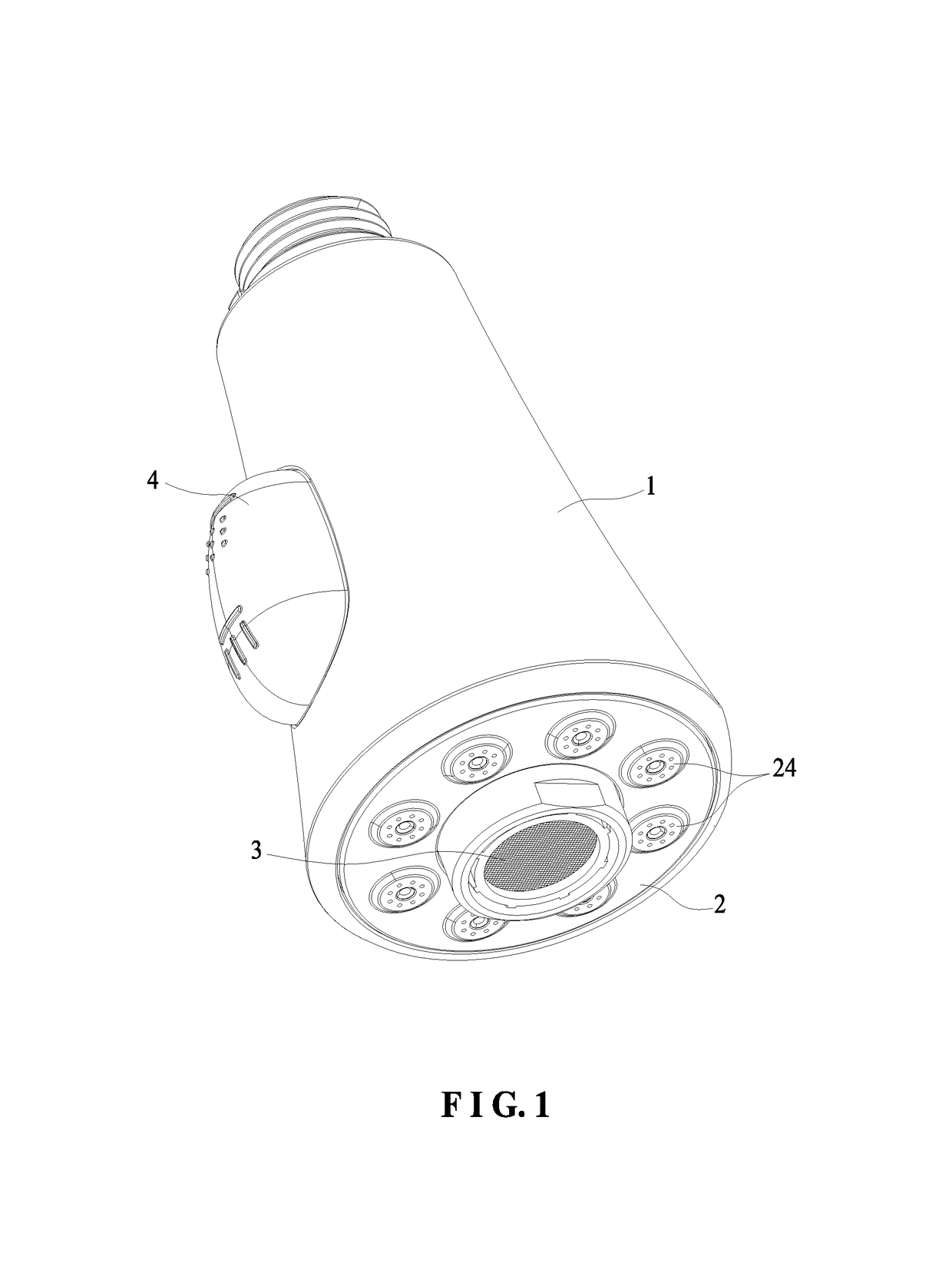
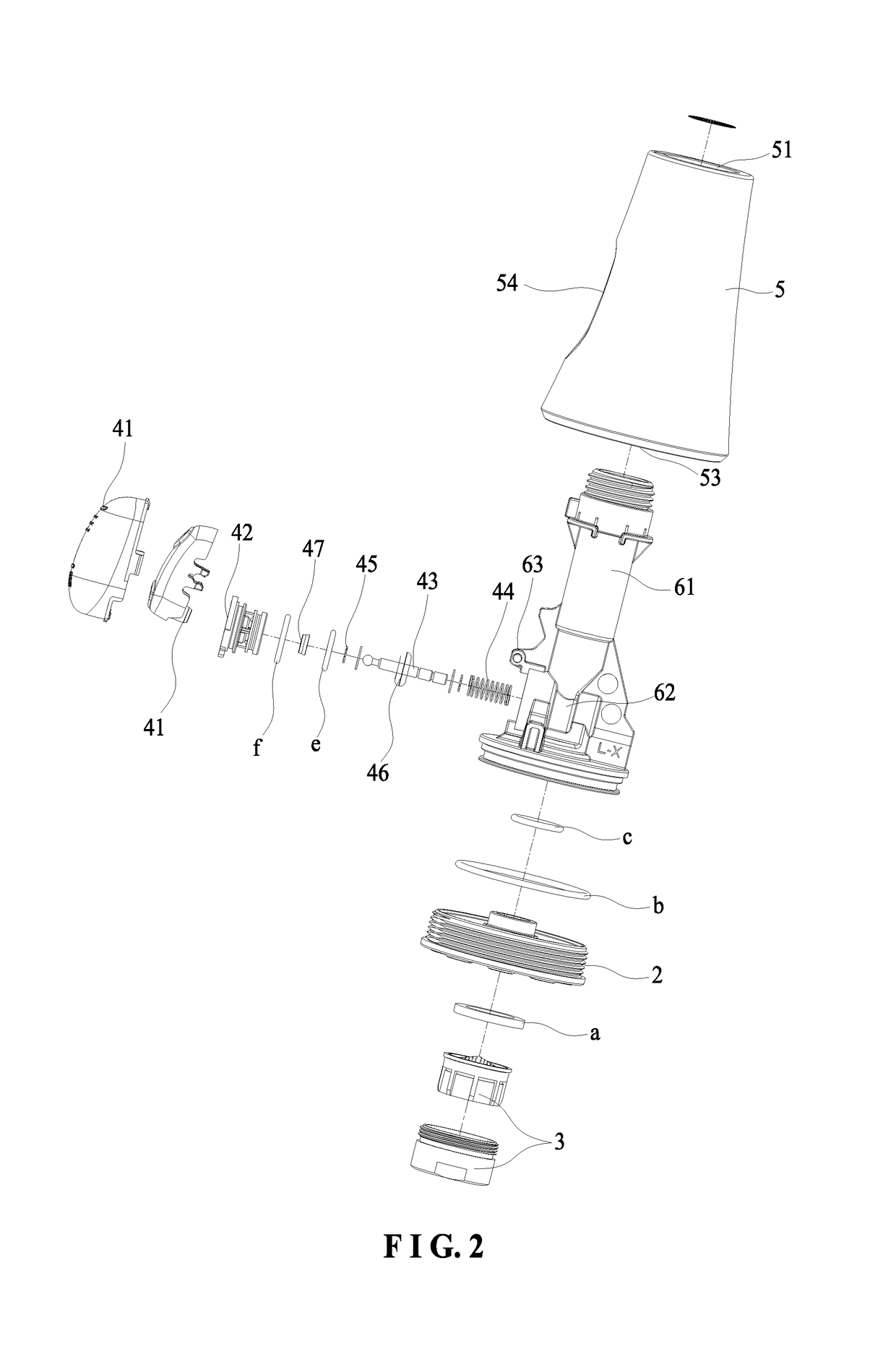
[0027]As shown in FIG. 1 to FIG. 10, the present invention discloses a shower head structure. The shower head structure comprises a main body 1, a face plate 2, a bubbler 3 installed in the middle portion of the face plate 2, and a switching device 4 installed inside the main body 1 for controlling an outflow of water from the face plate 2.

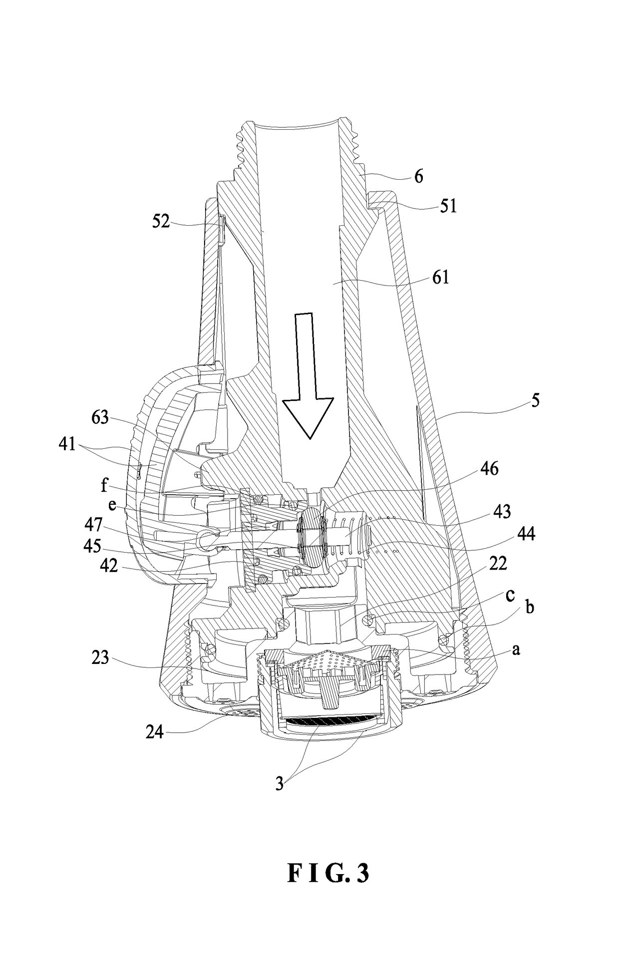
[0028]The center of the front of the face plate 2 has an installation trough 21 for installation of the bubbler 3. The bubbler 3 is screwedly connected to the installation trough 21. A searing ring a is provided between the bubbler 3 and the installation trough 21. The center of the back of the face plate 2 has a cylindrical first outlet chamber 22 communicating with the installation trough 21. The back of the face plate 2 further has an annular second outlet chamber 23.

[0029]The circumferential portion of the front...


PUM


Abstract

A shower head structure includes a main body, a face plate, and a switching device installed inside the main body for controlling an outflow of water from the face plate. The circumferential portion of the face plate is provided with a plurality of water outlet units. Each water outlet unit includes a plurality of jet orifices. The water flowing from the plurality of jet orifices forms a bunched spout. The bunched spout includes a plurality of fine spouts. The water won't spray about. Since the diameter of the jet orifice is small, the force of the fine spouts is stronger. The water-saving effect is good. The shower head can be used for low pressure environment.

Description

BACKGROUND OF THE INVENTION1. Field of the Invention[0001]The present invention relates to a bathroom accessory, and more particularly to a shower head structure able to flow out a bunched spout of water.2. Description of the Prior Art[0002]With the social development and the improvement of people's living standards, people pay more and more attention to the quality of life and also pay more attention to the environmental-friendly products. For taking a shower, people began to pay attention to the feeling of the water flow and the water-saving effect. The outflow of water of the existing shower head is unable to provide physical ease and relaxation. The water sprays about, and the water-saving effect is not good.[0003]Accordingly, the inventor of the present invention has devoted himself based on his many years of practical experiences to solve this problem.SUMMARY OF THE INVENTION[0004]The primary objective of the present invention is to provide a shower head structure which can in...

Claims


Application Information

Patent Timeline
Patent Type & Authority Patents(United States)
IPC IPC(8): B05B1/16B05B12/00B05B1/18E03C1/084
CPCB05B1/1609B05B1/1681E03C1/084B05B12/002B05B1/185E03C1/04E03C1/0408E03C1/0409E03C2001/0415Y02A20/411B05B1/1618B05B15/40
Inventor WANG, XUEDONGZHANG, JIANGCHENGWU, YUZHENG
Owner XIAMEN LOTA INT CO LTD
Why Eureka
Try Eureka