Nuclear grade air accumulating, isolating, indicating and venting device

a technology of indicating venting device and nuclear grade air, which is applied in the direction of functional valve types, nuclear elements, greenhouse gas reduction, etc., can solve the problems of failure of reactor coolant pump in a similar manner, failure of the system to prevent that fuel damage, and failure of the reactor coolant pump, so as to avoid stress corrosion cracking, improve the serviceability of the present device, and facilitate the effect of maintenan

Active Publication Date: 2018-12-18
NUCCORP
View PDF5 Cites 2 Cited by
  • Summary
  • Abstract
  • Description
  • Claims
  • Application Information

AI Technical Summary

Benefits of technology

[0016]The present device may be made without welds, by machining its major components from a single cylinder of steel. A weld-free device avoids stress corrosion cracking in the harsh environment of a nuclear reactor.
[0018]Still another feature of the present device may be a second set of flanges above the standpipe that allows replacement of the float or standpipe without replacement of the vent or system pipe coupling. This feature in combination with the isolation valve, dramatically improves serviceability of the present device. Servicing is simpler, faster, and with greatly reduced personal exposure to the radioactive environment of the interior of a nuclear reactor containment.
[0019]Finally, another feature of the present device is sizing of the coupling and standpipe of the present device so that it is large enough so that the water level is always visible on the scale regardless of changes in system pressure to thereby confirm that the system pipe is solid water and no gas remains in it. System pressure may range from ambient air pressure to approximately 3600 psi. As long as the water level is visible on the scale (and the isolation valve is open), all local gas in the pipe system has been accumulated and is safely isolated from the system.

Problems solved by technology

Air and gas accumulation in these fluid systems could result in failure of these systems and, in their failure, in turn failure to prevent that fuel damage.
The problem is common to Pressurized Water Reactors (PWRs), Boiling Water Reactors (BWRs), Small Modular Reactors (SMRs), Pebble Bed Modular Reactors (PBMRs), and International Reactor Innovative and Secure reactors (IRIS) and all other designs.
It is common knowledge that in 2011 the damage to reactors at Japan's Fukushima Daiichi power station resulted from a Loss Of Coolant Accident (LOCA).
A tsunami knocked out electric power to the plant and also flooded the backup generators needed to run the pumps that cool the reactor core.
What is less common knowledge is that gas voids in the cooling systems in every existing nuclear plant could also cause those reactor coolant pumps to fail in a similar manner.
When a gas void is introduced to a high speed pump, it creates a cavitation shock wave that can destroy the pump and damage instrumentation.
These solutions are unsatisfactory because they require radiation exposure of workers and / or the release of potentially contaminated liquids when there may not have been a need for testing or venting.
Also, UT probes, in general, cannot remain connected to the piping system in question due the temperature limitations of the UT equipment and associated coupling material.
As a consequence, they must be connected each time a UT examination is to be performed, thus taking additional time and resulting in additional exposure of workers to radiation.
Additionally, ultrasonic testing is both time-consuming and expensive for the utility.
Additionally, the logistics required to support these efforts and the costs charged to the utility that result from radiation exposure are substantial.
Many events result from human error when using ultrasonic testing.
The magnitude of the problem combined with the complication and expense of ultrasonic testing has led to an enormous problem for plant operators and owners.
Monthly monitoring by ultrasonic testing does not allow adequate trending frequency analysis to determine if gas accumulation is a result of natural air / gas accumulation or an air leak from a valve within the system.
However, these solutions use materials and construction practices that fail to meet the needs of the highly specialized requirements of the commercial nuclear industry, particularly if a device is to penetrate the pressure boundary of fluid piping systems.
Additionally, none of the existing methods provides a means of instantly isolating the gas as it accumulates while still allowing for routine maintenance and inspections while the supported cooling system is still in full operation.
None of these systems provides a means of determining the natural frequency of gas build-up within the system.
With data available on only a monthly basis, trending is difficult.
When gas is discovered, root cause analysis becomes difficult or even impossible.
The station may discover a gas void that was caused by a single event in the previous 29 days or that the frequency of the accumulation may have changed dramatically due to a leak.
Regardless, with the existing state of the art, trending analysis is hindered significantly.

Method used


Image

  • Nuclear grade air accumulating, isolating, indicating and venting device
  • Nuclear grade air accumulating, isolating, indicating and venting device
  • Nuclear grade air accumulating, isolating, indicating and venting device

Examples


Embodiment Construction

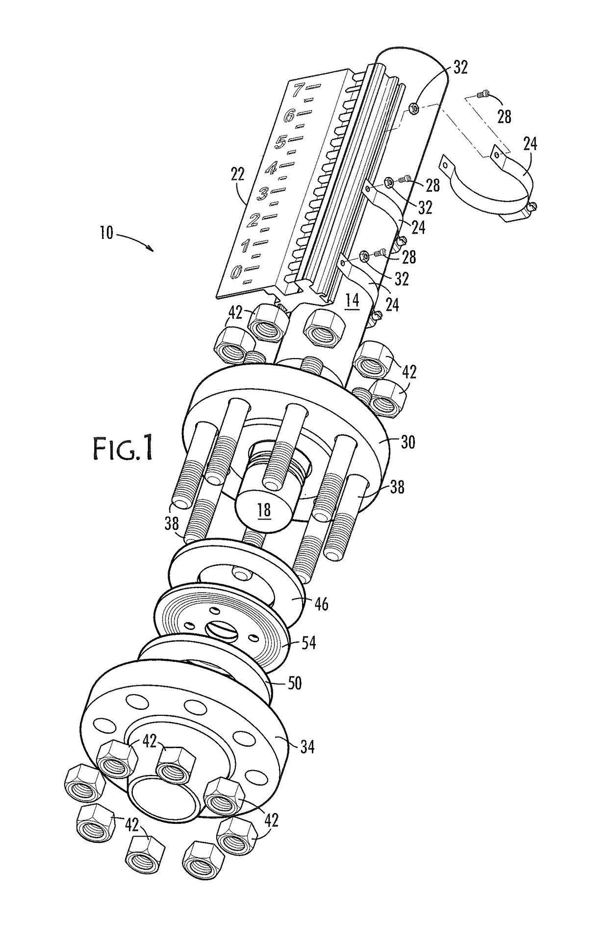
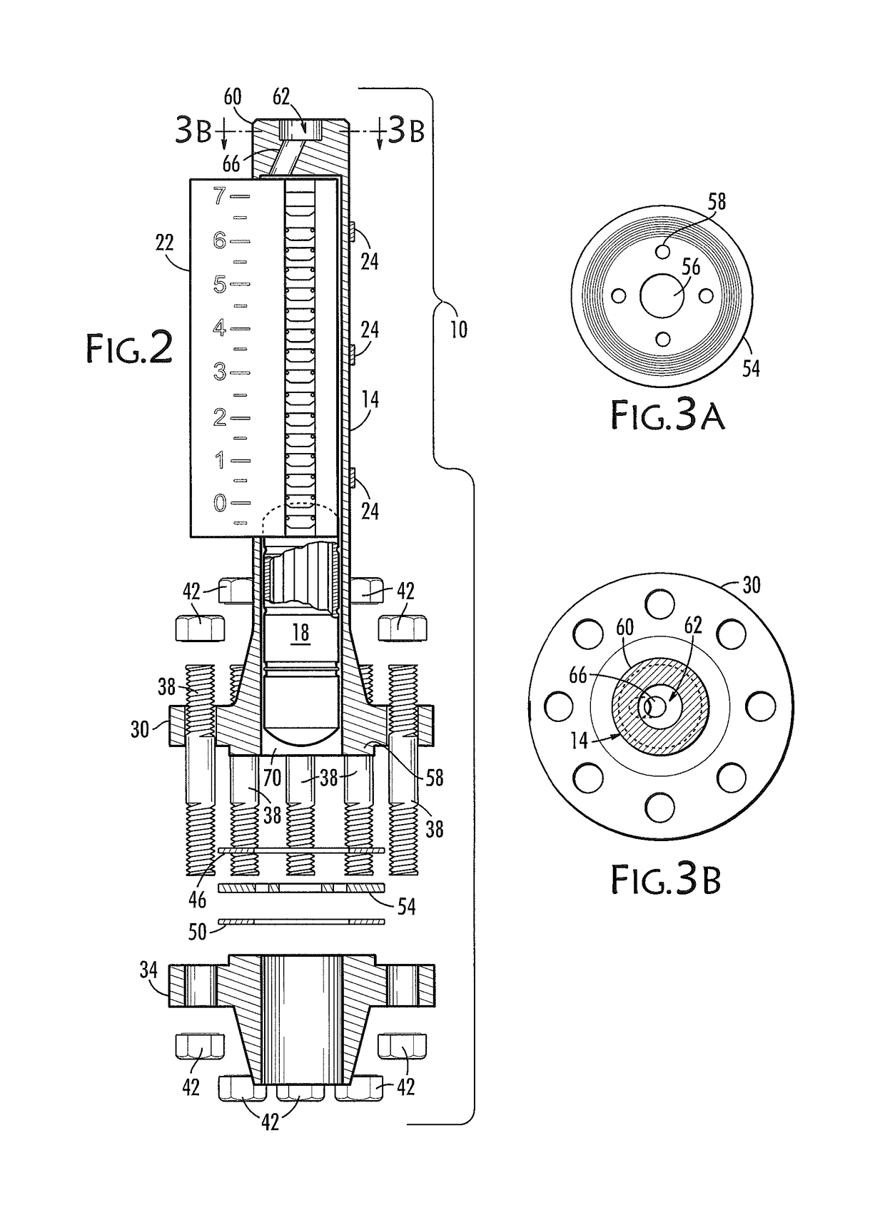
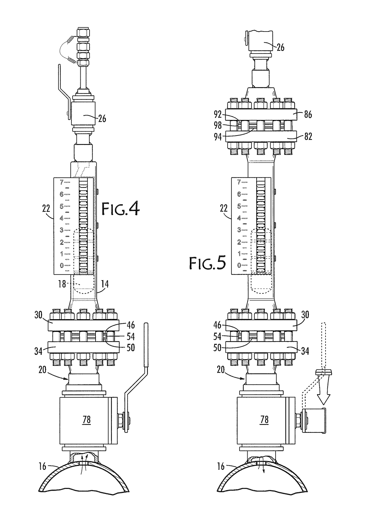
[0028]Referring now to FIGS. 1-5, the present invention is directed to a gas accumulating, isolating, indicating and venting device, generally referred to by reference number 10, for use in venting gas from an otherwise fluid-filled piping system. Device 10 is intended to be connected to a system pipe 16 (FIGS. 4 and 5) containing a fluid under pressure, and ideally connected to system pipe 16 at a local high point in elevation with respect to the adjacent balance of system pipe 16 so that the interior of device 10 is in fluid communication with the interior of system pipe 16. Device 10 extends above that high point via a coupling 20 so that gas in system pipe 16 will rise to that high point and from there flow through a hole made in system pipe 16 into coupling 20 and thence to a standpipe 14 where it will accumulate and remain isolated from the system until it is vented. The gas remains accumulated and is isolated by its own buoyancy. Even if the underlying system pipe 16 is calle...


PUM


Abstract

A device for isolating, accumulating, indicating and venting gas in a fluid system pipe includes a coupling affixed to a system pipe. The coupling includes an isolation valve. A standpipe is attached to the coupling. The standpipe holds a float trapped between a flow retaining orifice and a closed upper end save for an angled hole therein that allows gas to flow around the float. An indicator exterior to the pipe indicates the float's level in the standpipe regardless of system pressure changes. A vent valve attached above the standpipe allows controlled ventilation of the gas flowing from the system pipe through the standpipe and through the vent valve. Accumulation of gas from the system pipe lowers the float in the standpipe, at which point the user vents the gas, causing the float to rise with the rising fluid level.

Description

BACKGROUND OF THE INVENTION[0001]The present invention relates generally to the operation of fluid piping systems. More particularly, the present invention relates to keeping fluid piping systems free of air and other gases.[0002]Since the advent of commercial nuclear power in the late 1960's, the industry has been aware of issues regarding the accumulation of air and other gases in the high points in various safety-related fluid systems. These systems are designed to prevent nuclear fuel damage given various postulated accident scenarios. Air and gas accumulation in these fluid systems could result in failure of these systems and, in their failure, in turn failure to prevent that fuel damage.[0003]Among the many different manufacturers and different designs of nuclear power plants, there are substantial commonalities. One of those commonalities is the need to eliminate air accumulation from within the safety-related fluid systems. The problem is common to Pressurized Water Reactors...

Claims


Application Information

Patent Timeline
Patent Type & Authority Patents(United States)
IPC IPC(8): G21C19/28F16K24/04G21D1/02G21C17/022F16K37/00
CPCG21C19/28F16K24/044F16K37/0016G21D1/02G21C17/022Y02E30/40G21Y2002/50G21Y2004/30Y02E30/00Y02E30/30
Inventor WOOD, JR., WILLIE TURNERECHERER, SCOTT J.
Owner NUCCORP
Why Eureka
Try Eureka