A nuclear facility stainless steel cladding structure and construction technology

A construction technology, stainless steel technology, applied in covering/lining, building structure, construction, etc., can solve the problems of difficulty in ensuring the cleanliness of the back of the stainless steel cladding, economic loss, high dryness requirements, etc., and achieve long-term stability. , To ensure the quality of radiographic inspection, to ensure the effect of construction cleanliness

Active Publication Date: 2017-07-25
CHINA NUCLEAR POWER ENG CO LTD
View PDF4 Cites 0 Cited by
  • Summary
  • Abstract
  • Description
  • Claims
  • Application Information

AI Technical Summary

Problems solved by technology

[0007] The first disadvantage is that the current secondary concrete construction is difficult to ensure the cleanliness of the back of the stainless steel cladding, and the gap between the stainless steel cladding and the splicing embedded parts is prone to retain debris, which often leads to excessive radiographic inspection of the welded stainless steel cladding welds and difficult repairs.
Secondly, the secondary concrete construction needs to strictly control chloride ions and halogen elements to avoid possible stress corrosion of the stainless steel cladding, which will lead to increased construction costs
Due to lack of strict control of chloride ions and halogen elements due to extensive management and construction, etc., corrosion and leakage of stainless steel cladding of nuclear facilities often occur after nuclear facilities have been in operation for several years or more than ten years, resulting in additional outages and maintenance. lead to large economic losses
Third, in order to ensure the quality of the paint film when painting the surface of the concrete for the second time, there are higher requirements on the surface of the concrete such as the degree of dryness, which leads to a longer construction period
However, the quality and life of the paint film are affected by factors such as paint varieties and construction operations, which are often not easy to maintain for a long time, which is quite different from the life of nuclear facilities in decades.

Method used


Image

  • A nuclear facility stainless steel cladding structure and construction technology
  • A nuclear facility stainless steel cladding structure and construction technology
  • A nuclear facility stainless steel cladding structure and construction technology

Examples


Embodiment 1

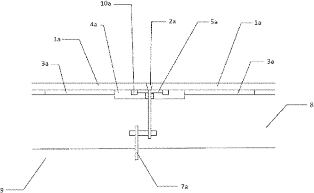
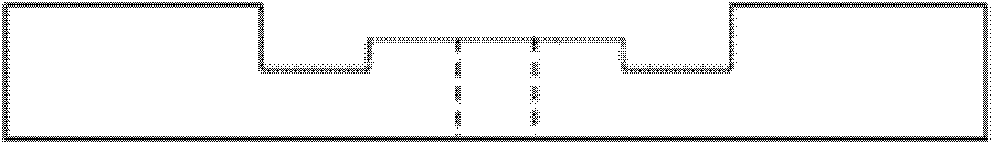
[0054] Such as figure 1 As shown, the nuclear facility stainless steel cladding structure provided in this embodiment includes a primary concrete foundation 9 and a secondary concrete 8, and a stainless steel cladding anchor 7a is installed on the primary concrete foundation 9, and the stainless steel cladding anchor 7a extends upward and passes through the secondary concrete. Concrete 8. The upper surface of the secondary concrete 8 is paved with ceramic components. The ceramic components are divided into common ceramic components 3a, ceramic components 4a at the lower part of the stainless steel cladding and spliced ​​welds, and some special-shaped ceramic components. Ordinary ceramic components 3a are square, and special-shaped ceramic components can be laid on the corners of the pool or around the embedded parts of the pool as required. The structure of the ceramic member 4a at the bottom of the stainless steel cladding installation stitching weld is as follows figure 2...

Embodiment 2

[0062] Such as Figure 5 As shown, the nuclear facility stainless steel cladding structure provided in this embodiment includes a primary concrete foundation 9 and a secondary concrete 8. A stainless steel cladding anchor 7b is installed on the primary concrete foundation 9, and the stainless steel cladding anchor 7b extends upward and passes through the secondary concrete. Concrete 8. In this embodiment, the stainless steel cladding anchors 7b can be arranged in pairs. The upper surface of the secondary concrete 8 is paved with ceramic components. The ceramic components are divided into ordinary ceramic components 3b, ceramic components 4b at the lower part of the stainless steel cladding and spliced ​​weld, and some ceramic components with special shapes suitable for special parts. Ordinary ceramic components 3b are square, and special-shaped ceramic components can be laid on the corners of the pool or around the embedded parts of the pool as required. The structure of the...

Embodiment 3

[0070] Such as Figure 9 As shown, the nuclear facility stainless steel cladding structure provided in this embodiment includes primary concrete foundation 9 and secondary concrete 8, and stainless steel cladding anchor 7c is installed on primary concrete foundation 9, and stainless steel cladding anchor 7c extends upward and passes through secondary concrete. Concrete 8. The upper surface of the secondary concrete 8 is paved with ceramic components. The ceramic components are divided into common ceramic components 3c, ceramic components 4c at the lower part of the stainless steel cladding and splicing welds, and some special-shaped ceramic components. Ordinary ceramic components 3c are square, and special-shaped ceramic components can be laid on the corners of the pool or around the embedded parts of the pool as required. The structure of the ceramic component 4c at the lower part of the stainless steel cladding installation stitching weld is as follows Figure 10 , Figur...


PUM


Abstract

The invention belongs to the field of building structures, and in particular relates to a nuclear facility stainless steel cladding structure and a construction process. The stainless steel cladding structure includes stainless steel cladding, connectors, anchors, ceramic components and concrete, wherein the ceramic components are located between the stainless steel cladding and the concrete for use. The stainless steel cladding and concrete are isolated from each other. After adopting the nuclear facility stainless steel cladding structure of the present invention, the construction process can be simplified, the construction quality level can be improved, the construction period of the nuclear facility stainless steel cladding can be shortened, and the corrosion leakage of the stainless steel cladding can be reduced.

Description

technical field [0001] The invention belongs to the field of building structures, and in particular relates to a nuclear facility stainless steel cladding structure and construction technology. Background technique [0002] 304L stainless steel cladding is often used in the fuel storage and transfer building structures of nuclear facilities. The structure is usually primary concrete-anchor and splicing embedded parts / secondary concrete-dustproof paint-stainless steel cladding. The main construction technology is: [0003] -Install stainless steel cladding anchor-splicing embedded parts on primary concrete; [0004] -Secondary concrete construction, including opening drainage channels; [0005] - Painting on secondary concrete surfaces (including concrete drying, concrete surface treatment, painting, etc.); [0006] -Installation of welded stainless steel cladding on embedded parts. [0007] The first disadvantage is that the current secondary concrete construction is diff...

Claims


Application Information

Patent Timeline
Patent Type & Authority Patents(China)
IPC IPC(8): E04F13/077E04F13/076E04F13/24
Inventor 于坚张洪军
Owner CHINA NUCLEAR POWER ENG CO LTD
Why Eureka
Try Eureka