
Method of reducing corrosion of nuclear reactor structural material

a nuclear reactor and structural material technology, applied in the direction of greenhouse gas reduction, distance measurement, instruments, etc., can solve the problems of increasing the dose rate of the turbine system, the corrosion of the fuel material, and the need for additional equipment, so as to reduce the corrosion of the structural material of the nuclear reactor, suppress the flow of radioactivity, and prevent the cracking of stress corrosion

Active Publication Date: 2013-03-21
TOSHIBA ENERGY SYST & SOLUTIONS CORP
View PDF29 Cites 0 Cited by
  • Summary
  • Abstract
  • Description
  • Claims
  • Application Information

AI Technical Summary

Benefits of technology

The present invention provides a method for reducing corrosion of a nuclear reactor structural material by decreasing the amount of hydrogen injection for preventing stress corrosion cracking, which results in the reduction of excessive hydrogen in the off-gas system and suppression of melting of metal oxides near a noble metal. This method also prevents the flowing of radioactivity into the turbine system and reduces corrosion of the fuel material, which suppresses the increasing in the amount of hydrogen absorption. The method is particularly useful for BWR nuclear plant facilities. Overall, the present invention effectively reduces corrosion of the nuclear reactor structural material while minimizing the risks of increased dose rate in the turbine system and flowing of hydrogen into the off-gas system.

Problems solved by technology

Unfortunately, the resultant ammonia flows into a main steam, thereby increasing the dose rate in the turbine system.
Furthermore, since the injected hydrogen flows into an off-gas system, it is necessary to carry out a reaction to recombine the hydrogen with oxygen, and therefore, additional equipment is required.
This adhesion causes corrosion of the fuel material or increases the amount of hydrogen absorption.
In addition, at a portion to which the noble metal is deposited, when the hydrogen molar concentration is double or more of the oxygen molar concentration, the corrosion potential of the material drastically decreased.
Such a significant decrease in the corrosion potential impairs the stability of the oxide film formed on the surface of the material.
Moreover, when the above noble metal chemical addition is performed in nuclear power plants, a large amount of noble metal adheres to a zirconium oxide film of the fuel.
As a result, this adhesion increases the oxidation and hydrogenation of the fuel material.
As described above, the noble metal chemical addition causes negative effects in the water quality conservation, the decrease in the flowing of radioactivity and the increase in burn-up of the fuel.
Therefore, the application range of anticorrosion is limited to a structural material in the reactor such as a shroud, and unfortunately, a sufficient anticorrosion effect cannot be expected in other components such as primary loop recirculation system piping.

Method used


Image

  • Method of reducing corrosion of nuclear reactor structural material
  • Method of reducing corrosion of nuclear reactor structural material
  • Method of reducing corrosion of nuclear reactor structural material

Examples


first embodiment

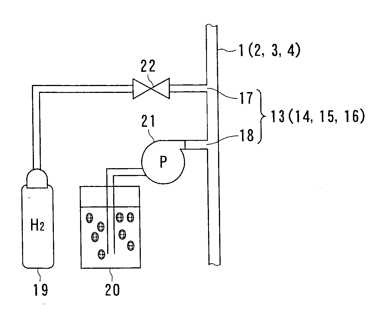
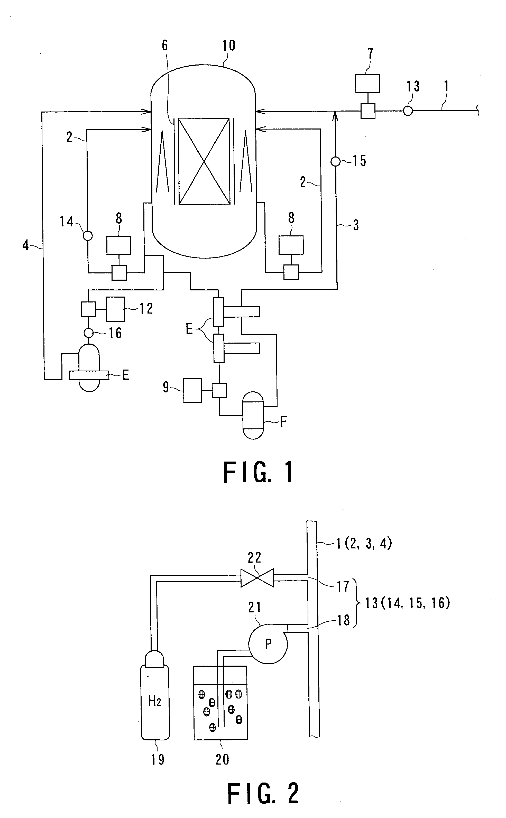
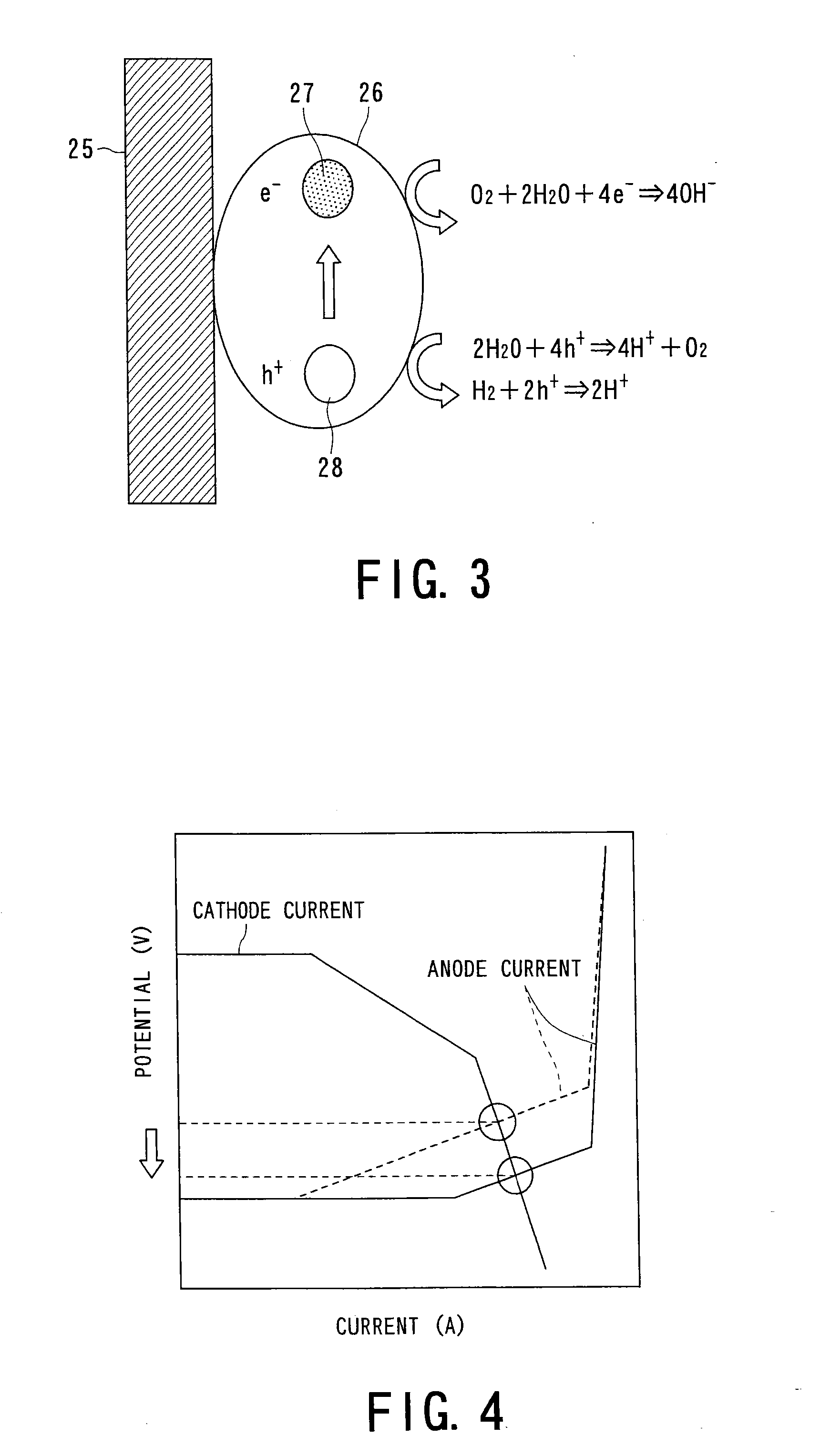
[0055]A first embodiment of the method of reducing corrosion of a material constituting a nuclear reactor structure (which may be called hereunder “nuclear reactor structural material”) according to the present invention will be first described with reference to FIGS. 1 to 4.

[0056]FIG. 1 shows a circulating system of reactor water in a nuclear power plant. This reactor water circulating system includes a reactor pressure vessel 10, a feed water system piping 1, a primary loop recirculation (PLR) system piping 2, a reactor water clean-up (RWCU) system piping 3, and a residual heat removal (RHR) system piping 4. Examples of a nuclear reactor structural material forming the reactor pressure vessel 10 include materials of a shroud 6 shown in FIG. 1, a core support plate, and a grid plate. The method of reducing corrosion of a nuclear reactor structural material of the present invention can be applied to such materials.

[0057]A feed water pump 7 is disposed in the feed water system piping...

second embodiment

[0067]A second embodiment of the present invention will be described hereunder with reference to FIGS. 5 to 10.

[0068]FIG. 5 shows a circulating system of cooling water in a nuclear power plant. In this circulating system, equipment for setting test pieces for sampling is connected to the circulating system shown in FIG. 1. In FIG. 5, the same components as those in FIG. 1 have the same reference numerals. The description of the structure composed of the same components is omitted herein.

[0069]Referring to FIG. 5, test pieces 31 for monitoring the adhesion amount are disposed in a branch line formed in the vicinity of the injection point 14 of the primary loop recirculation (PLR) system pipe 2. Valves 32 and 33 (e.g., stop valves), which can isolate the test pieces 31 from the circulating system during sampling, are disposed at the upstream and the downstream of the branch line including the test pieces 31.

[0070]The adhesion amount of the titanium oxide to the structural material is ...


PUM

PropertyMeasurementUnit
molar ratioaaaaaaaaaa
electrochemical corrosion potentialaaaaaaaaaa

Abstract

In a method of reducing corrosion of a material constituting a nuclear reactor structure, an electrochemical corrosion potential is controlled by injecting a solution or a suspension containing a substance generating an excitation current by an action of at least one of radiation, light, and heat existing in a nuclear reactor, or a metal or a metallic compound forming the substance generating the excitation current under the condition in the nuclear reactor to allow the substance generating the excitation current to adhere to the surface of the nuclear reactor structural material, and by injecting hydrogen in cooling water of the nuclear reactor while controlling the hydrogen concentration in a feed water.

Description

CROSS-REFERENCE TO RELATED APPLICATIONS[0001]This application is a divisional application of, and claims the benefit of priority under 35 U.S.C. §120 from, U.S. application Ser. No. 11 / 008,288, filed Dec. 10, 2004, herein incorporated by reference, which claims the benefit of priority under 35 U.S.C. §119 from Japanese Patent Application No. 2003-435120, filed Dec. 26, 2003.BACKGROUND OF THE INVENTION[0002]1. Field of the Invention[0003]The present invention relates to a method of reducing corrosion of a nuclear reactor structural material composed of a stainless steel or a nickel-base alloy, which is used in a nuclear power plant such as boiling water reactor (BWR).[0004]2. Related Art[0005]In a boiling water reactor (BWR) plant widely operated in the world, the cooling water contains a high concentration of oxidizing species or oxidizers such as oxygen and hydrogen peroxide which are generated by radiolysis of reactor water. Therefore, it is known that stress corrosion cracking (S...

Claims


Application Information

Patent Timeline
Patent Type & Authority Applications(United States)
IPC IPC(8): G21C9/00C23FG21C19/307G21C3/07G21C3/20G21D1/00G21D3/08
CPCG21C3/324Y02E30/40G21C9/00G21Y2002/103Y02E30/30Y02E30/00C23F11/18C23F11/185C23F11/187G21C3/07G21C3/20G21C19/00G21C19/307G21D3/08
Inventor YAMAMOTO, SEIJIYOTSUYANAGI, TADASUICHIKAWA, NAGAYOSHIOOSATO, TETSUOOKAMURA, MASATOTAKAGI, JUNICHIYAMAZAKI, KENJISUZUKI, SHUNICHITAKAMORI, KENROSAMBONGI, MITSURUSHIBANO, TAKESHIHIRANO, TAKASHIFUKAYA, YUICHI
Owner TOSHIBA ENERGY SYST & SOLUTIONS CORP
Learn More