Compensating electrical harmonics on the electrical grid

a technology of electrical harmonics and electrical grids, applied in the direction of reducing harmonics/ripples in the ac network, reactive power adjustment/elimination/compensation, single network parallel feeding arrangement, etc., can solve the problem of harmonic distortion on the grid, harmonic distortion may be particularly generated, and the cost of passive filters is high and requires a relatively large spa

Active Publication Date: 2018-12-18
VESTAS WIND SYST AS
View PDF0 Cites 0 Cited by
  • Summary
  • Abstract
  • Description
  • Claims
  • Application Information

AI Technical Summary

Benefits of technology

[0006]It would be advantageous to achieve improvements in methods for compensating electrical harmonics on the electrical grid. In general, the invention preferably seeks to alleviate or eliminate one or more of the above mentioned disadvantages relating to known systems for filtering undesired harmonics. In particular, it may be seen as an object of the present invention to provide a method that solves the above mentioned problems relating to harmonic grid distortion, or other problems, of the prior art.
[0010]Advantageously, the harmonic compensator may be configured to determine control input on basis of one or more resonance frequencies so that compensation of electrical harmonics at one or more different resonance frequencies is possible.

Problems solved by technology

The harmonic distortion on the grid is caused due to variations of harmonic grid impedance due to switching of grid connected elements such as load, capacitors, reactor banks and generators of power producing units connected to the grid.
However, passive filters are expensive and require relatively large space.
Harmonic distortion may particularly be generated by wind turbine generators, solar power generators, hydro electric generators or generators or other power producing units.

Method used


Image

  • Compensating electrical harmonics on the electrical grid
  • Compensating electrical harmonics on the electrical grid
  • Compensating electrical harmonics on the electrical grid

Examples


Embodiment Construction

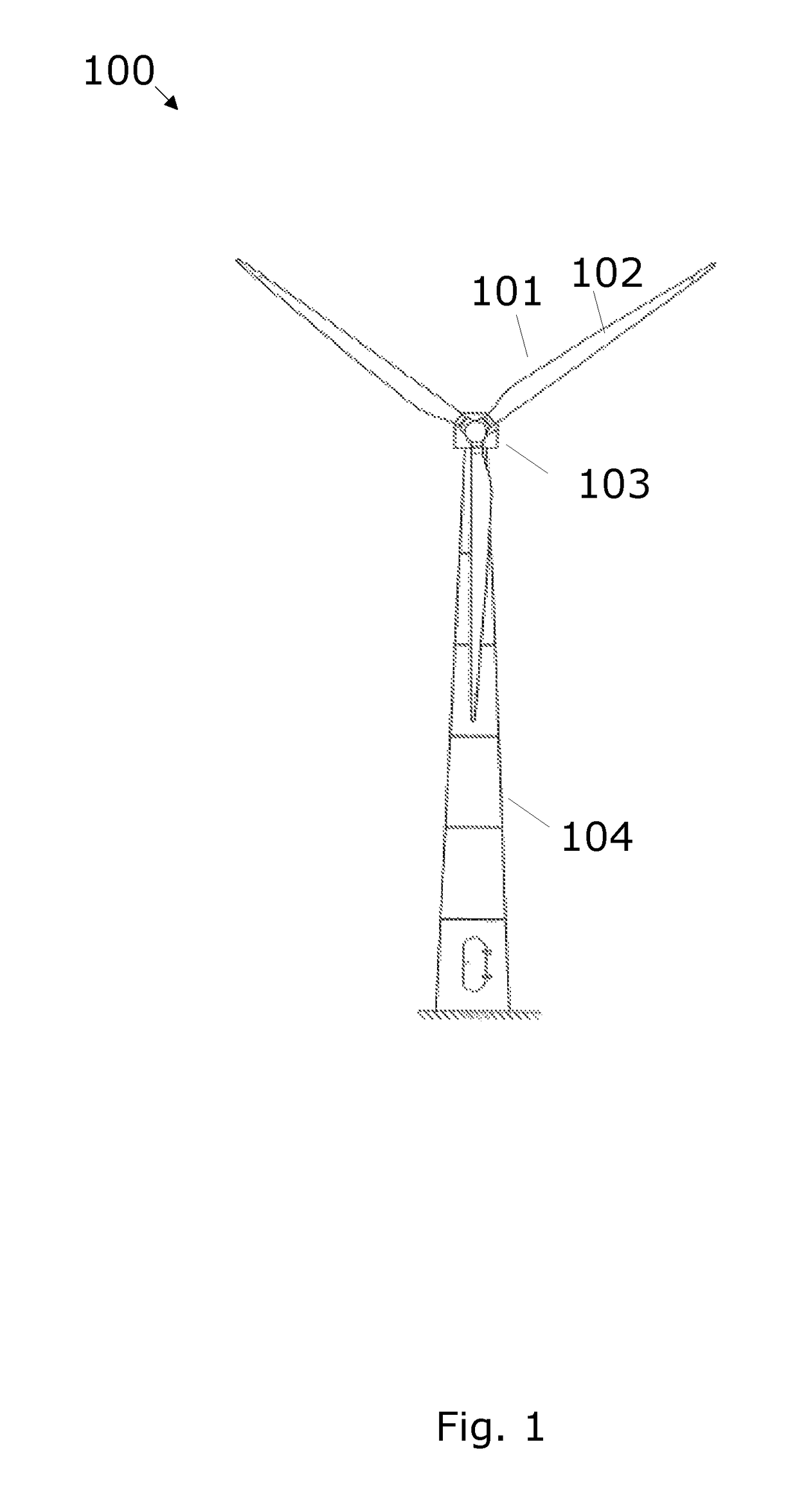
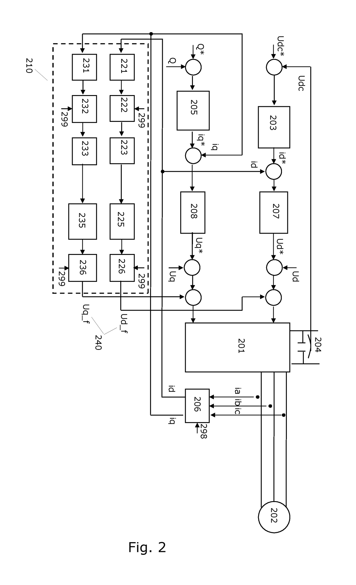
[0042]FIG. 1 shows a wind turbine generator 100, hereafter also referred to as a WTG. The WTG 100 includes a rotor 101 for driving a shaft coupled to a power generator for generation of electric power from the wind driven rotor 101. A gearbox may connect a shaft of the rotor 101 to a shaft of the generator. Output power from the generator may be converted by a power converter, e.g. in frequency, before being supplied to a utility grid (electrical grid). The power converter includes an AC-to-DC converter and a DC-to-AC converter, the latter is referred to as an inverter 201 (see FIG. 2). The gear box, the generator and / or the power converter may be located in a nacelle 103. The nacelle 103 and rotor 101 is located on top of a tower 104. The WTG further includes a control system for controlling the inverter's 201 injection of active and reactive current to the utility grid and a harmonic compensator 210 for generating control input signals for the inverter so that the current injected...


PUM


Abstract

The invention relates to a control system for compensating undesired electrical harmonics on an electrical grid. Part of the control system referred to as a harmonic compensator is operatively connected with a power inverter of a power producing unit supplying power to the grid. Another part of the control system, referred to as an impedance detector, is operatively connected to a point of coupling to which point one or more power producing units are connected. The impedance detector is configured to scan impedances as a function of frequency to identify frequencies of impedance peaks which peaks are indicative of resonance frequencies. The determined resonance frequencies are supplied to one or more the harmonic compensators. A compensator determines control signals to the inverter which causes the inverter to inject compensation currents to the grid which currents will damp currents oscillating at or close to the determined resonance frequency.

Description

FIELD OF THE INVENTION[0001]The invention relates to compensating electrical harmonics on the electrical grid, particularly to controlling power converters of power generating units for compensating electrical harmonics on the electrical grid.BACKGROUND OF THE INVENTION[0002]The harmonic distortion at the Point of Common Coupling on the electrical grid has to be within the limits specified e.g. by a grid code specification. The harmonic distortion on the grid is caused due to variations of harmonic grid impedance due to switching of grid connected elements such as load, capacitors, reactor banks and generators of power producing units connected to the grid.[0003]Use of passive filters for filtering undesired harmonics is possible. However, passive filters are expensive and require relatively large space.[0004]Harmonic distortion may particularly be generated by wind turbine generators, solar power generators, hydro electric generators or generators or other power producing units.[00...

Claims


Application Information

Patent Timeline
Patent Type & Authority Patents(United States)
IPC IPC(8): H02J3/01H02J3/18H02J3/38H02M1/12G01R19/00H02M7/44G01R27/02
CPCH02J3/01G01R19/0092G01R27/02H02J3/1842H02J3/382H02J3/386H02M1/12H02M7/44H02J3/383Y02E40/22Y02E10/763H02J2300/28H02J3/381Y02E10/56Y02E10/76Y02E40/20H02J3/46
Inventor GUPTA, AMIT KUMARGUPTA, MANOJGURU, DILIP KUMAR
Owner VESTAS WIND SYST AS
Why Eureka
Try Eureka