Scanbody

a scanning body and scanning technology, applied in the field of dental care, can solve the problems of affecting the quality of scanning, the work of scanning media, and the loss of alignment, so as to improve the accuracy and reliability of scanning models with analogs, minimize, or eliminate, and reduce the formation of artifacts

Active Publication Date: 2018-12-25
JJGC IND COMERCIO DE MATERIAIS DENTARIOS
View PDF38 Cites 4 Cited by
  • Summary
  • Abstract
  • Description
  • Claims
  • Application Information

AI Technical Summary

Benefits of technology

[0021]One or more embodiments of the invention include a scanbody that provides improvements in scanbody performance based on raw material and external geometry. Regarding raw material, at least one embodiment of the invention includes an effect on opaque material that may be used in CAD / CAM scanners, which is used to dispense powder or spray application during a scanning process. Regarding geometry, one or more embodiments provide a geometry that favors the scanning in all regions of the mouth with the correct identification of a position, direction and rotation of the implant or implant analogs. In at least one embodiment, the scanbody may be asymmetrical to ensure the correct identification of the position, direction and rotation of the analogs, without generating any asymmetry measurement errors.
[0022]One or more embodiments of the invention include a scanbody geometry used during a scanning procedure that minimizes, or eliminates, the formation of artifacts, such as errors, during the scan. As such, in at least one embodiment, the accuracy and reliability of the scanning of models with analogs is increased, thus facilitating the manufacture of prosthetic structures. At least one embodiment of the invention may eliminate the use of non-reflective powders or opacificator sprays during the scanning process.
[0023]One or more embodiments of the invention may include assembling a scanbody that only includes rounded surfaces on the face of the scanbody to determine the rotational orientation of the workpiece and applying a dual-taper geometry design to the scanbody. At least one embodiment may include rounded surfaces instead of flat surfaces, such that the quality of data collection is improved, since such surfaces decrease the incidence of reflections on the scanner's capture element. One or more embodiments of the invention may include dual-taper geometry that forms the scan body, to enlarge the reading area without generating unwanted reflections, and to determine workpiece height more precisely. In at least one embodiment, the ability to recognize geometry may conveniently affect software needed for the scanning process, wherein less error correction routines are required during the scanning procedure.
[0024]One or more embodiments of the invention may include machining the part instead of manufacturing it by injection molding, wherein micro grooves resulting from the machining process helps increase scanbody surface opacity.

Problems solved by technology

Thus, typically, the screw that holds the connection to the abutment is used only to prevent the separation of these two parts and does not prevent the relative rotation movement among them, by minimizing the strain on the screw and expanding its cycle life.
This occurs because, even if the installation is carefully made to achieve a specific alignment, certain micro movements during the healing phase may lead to loss of alignment.
However, it is difficult to work with scanning media directly inside the mouth, especially due to access difficulties, limited space, poor lighting, and the presence of fluids (such as saliva), which cause undesired reflexes that may affect the quality of the scanning and compromise the accuracy of the measurement.
Capturing the anti-rotation element at the top of the implant when it might be hidden, in fluids or covered by close elements is particularly challenging, which frequently leads to errors that need to be later balanced.
The problem with typical scanners is that its geometry generates artifacts, also referred to as errors, during scanning.
Such artifacts occur due to the way the light emitted by scanners interacts with flat surfaces of the pieces.
Such errors are compensated in a post-processing step, which prolongs the scanning process.
Furthermore, when the piece does not present flat surfaces, as discussed in European Patent 2400917 to Eriksson et al., entitled “Device for Indicating the Position and Orientation of a Dental Implant”, it is not possible to locate the orientation of the anti-rotation element on the abutment head.
For example, the scanbody as presented in Eriksson et al., is also subject to problems in the identification of implant position and direction when it is set between remaining dental elements and only functions efficiently in the case of tooth loss.
Also, the material currently used in the making of scanners presents problems.
Metal used in several aforementioned manners is expensive and presents shiny surfaces after machining.
However, the injection process results in a nearly polished finishing, which highlights the shine problems, demanding the use of opaque sprays.
However, generally, PEEK does not present good performance during the scanning process due to reflection.

Method used


Image

  • Scanbody
  • Scanbody
  • Scanbody

Examples


Embodiment Construction

[0031]The following description is of the best mode presently contemplated for carrying out at least one embodiment of the invention. This description is not to be taken in a limiting sense, but is made merely for the purpose of describing the general principles of the invention. The scope of the invention should be determined with reference to the claims.

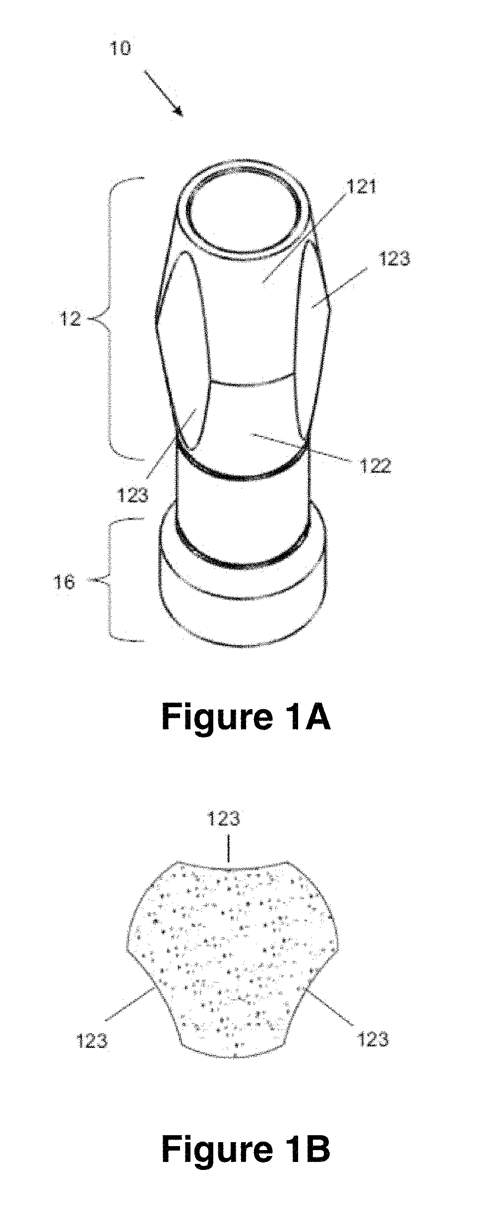
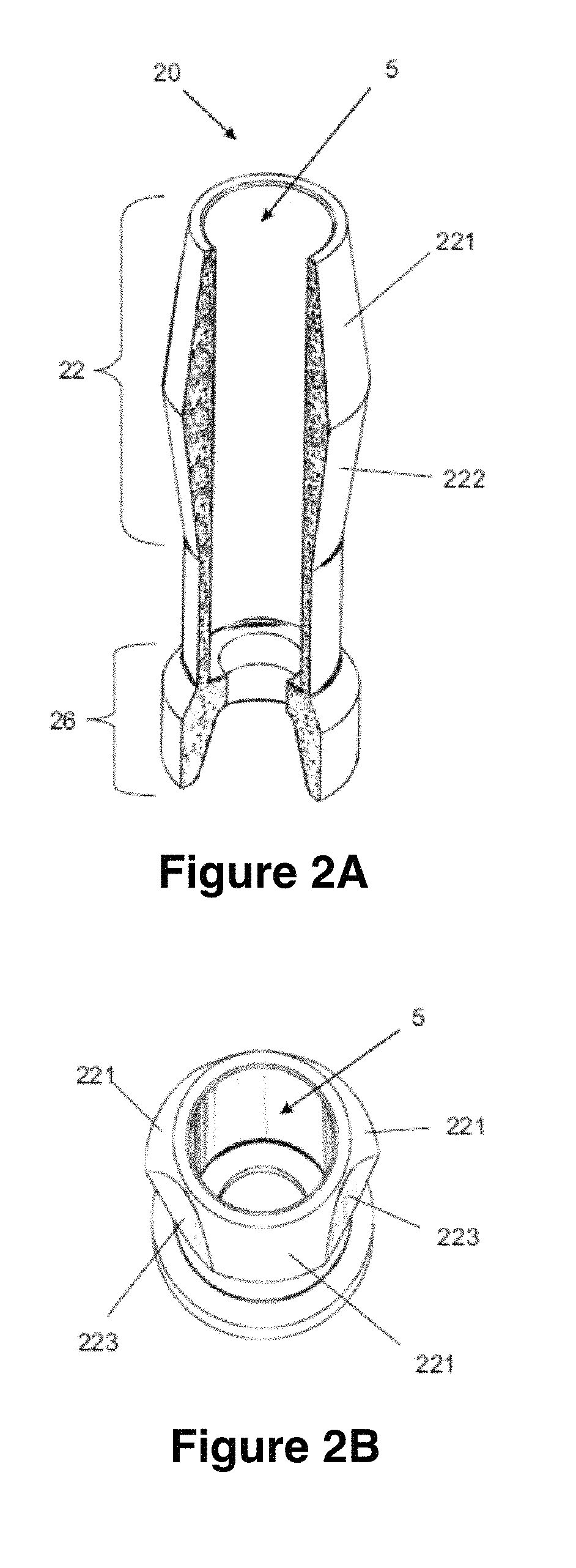
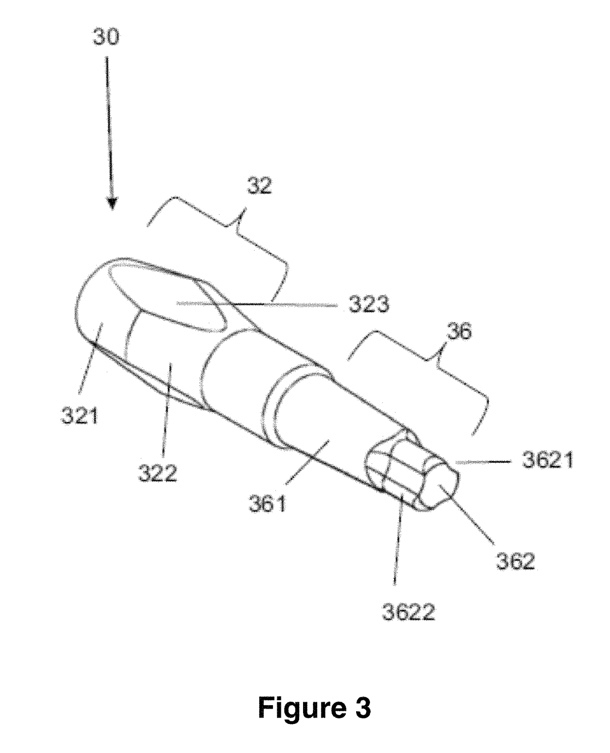
[0032]FIGS. 1A and 1B illustrate the main features of the scanbody device and a cross-section view of the scanbody device, according to one or more embodiments of the invention. At least one embodiment includes a scanning device (10) that includes a body (12) and a base (16) interconnected by a middle part to maintain a body and base set height constant when different types of anti-rotation elements are used.

[0033]In one or more embodiments, the base (16), as a lower part of the scanning device (10), may fit on a dental implant anti-rotation geometry, whether located in a fixing installed in a mouth of a user or analog attached to ...


PUM


Abstract

Embodiments include a scanbody that includes a base that fits in an anti-rotation geometry of a dental implant, and a body that is set to be scanner. The body includes a lateral surface with geometrical elements that allow the identification of information regarding a position, direction and rotation of the scanbody. The body lateral surface does not include any flat portion and includes a first opposing trunconical element, base-to-base, a secondary trunconic element and concave surfaces disposed at the side, including a hole (5) that receives a fixing screw.

Description

[0001]This application claims foreign priority to Brazilian Patent Application Serial No. 1020150184603, filed on 31 Jul. 2015, the specification of which is hereby incorporated herein by reference.BACKGROUND OF THE INVENTION[0002]Field of the Invention[0003]Embodiments of the invention generally relate to the field of dentistry and, specifically, to printing aided techniques used with dentures and molds for printing. Embodiments include a component that transfers position, direction and rotation information of an implant installed in a patient's mouth or in a mold to be used in scanning equipment.[0004]Description of the Related Art[0005]Generally, dental implants are used as supports to replace one or more missing teeth. The implant, also known as abutment, is typically the first of at least two parts of dental restoration that also includes one or more prosthetic elements fixed to the implant by means of a screw. The prosthetic elements are responsible for aesthetic replacement o...

Claims


Application Information

Patent Timeline
Patent Type & Authority Patents(United States)
IPC IPC(8): A61C8/00A61C9/00
CPCA61C8/0001A61C8/006A61C9/0053A61C8/0068A61C8/0071A61C8/0016A61B5/0088A61C9/004A61C9/0046A61C13/0004A61C19/04G05B19/4207
Inventor THOME, GENINHOTHOME, THIAGO VIEIRAMERTIN, FELIX ANDREAS
Owner JJGC IND COMERCIO DE MATERIAIS DENTARIOS
Why Eureka
Try Eureka