Cable loading structure

a loading structure and cable technology, applied in the direction of mechanical equipment, transportation and packaging, passenger handling equipment, etc., can solve the problems of increasing transportation costs, complex arrangement, and high production and maintenance costs, and achieve the effect of enhancing the self-sufficiency of the cable loading structure and accurate keying of the drive mechanism

Active Publication Date: 2019-01-01
JDR CABLE SYST
View PDF15 Cites 0 Cited by
  • Summary
  • Abstract
  • Description
  • Claims
  • Application Information

AI Technical Summary

Benefits of technology

[0012]With this arrangement, a cable storage tank can be received and loaded or unloaded without the need for specialist additional infrastructure on a quay or vessel to control the loading operation. By using a floating structure and a floating tank, the substantial weight of the tank is borne by the floatation on the water. This also avoids the need for any complex bearing arrangement to allow the tank to rotate to load or unload a cable. As the structure is also floating there is no issue with the height of the tank varying due to tidal movements as the structure will move broadly in tandem with the tank.
[0015]By engaging the tank with the structure, they can also be moved around together. This allows the tank and cable to be transported without having to unload and also without needing the infrastructure for unloading at the destination as this is provided by the cable loading structure itself.
[0016]Preferably the drive system uses one or more of the tank engaging means. In this way the tank engaging means can be used to rotate the tank during loading / unloading avoiding the need for further external means to rotate the tank.
[0017]The drive system is preferably arranged to engage the outer periphery of the tank. In this way, the engaging means can be biased against the tank to achieve a frictional force for the drive to be applied. Additionally, less force is needed to drive the outer periphery than trying to provide a drive to the inner parts of the tank or using a drive on the axis of the tank. This arrangement will also accommodate some limited slip due to relative movement of the tank and structure due to swell etc. This avoids the need for an accurately keyed drive mechanism.
[0018]The cable loading structure may include a loading arm arranged to transfer cable into or out of the tank. In this way, the cable loading structure can accurately position the cable in the tank and deliver the cable at the most appropriate location. For example, the cable may need to be delivered to a quayside which is higher than the tank level or alternatively, it may need to be delivered into the sea for direct laying on the seabed. By providing a loading arm on the structure, the self-sufficiency of the cable loading structure is enhanced.
[0023]Preferably, the tank engaging means are resiliently biased into engagement with the tank. In this way, when the tank is in the retained position, the tank engaging means are loaded against this resilience which will tend to increase the force applied to the tank and increase the reliability of the engagement between the tank and structure. It also increases the frictional force between the two such that any driving force applied to the tank can be transferred without slipping.

Problems solved by technology

However, due to the substantial loads involved and the size, such arrangements are generally complicated and costly to produce and maintain.
However there are disadvantages to such an arrangement.
Civil and mechanical engineering works are required on the quayside, which may not be permitted or welcomed by port authorities and may add to the transportation costs.

Method used


Image

  • Cable loading structure
  • Cable loading structure
  • Cable loading structure

Examples


Embodiment Construction

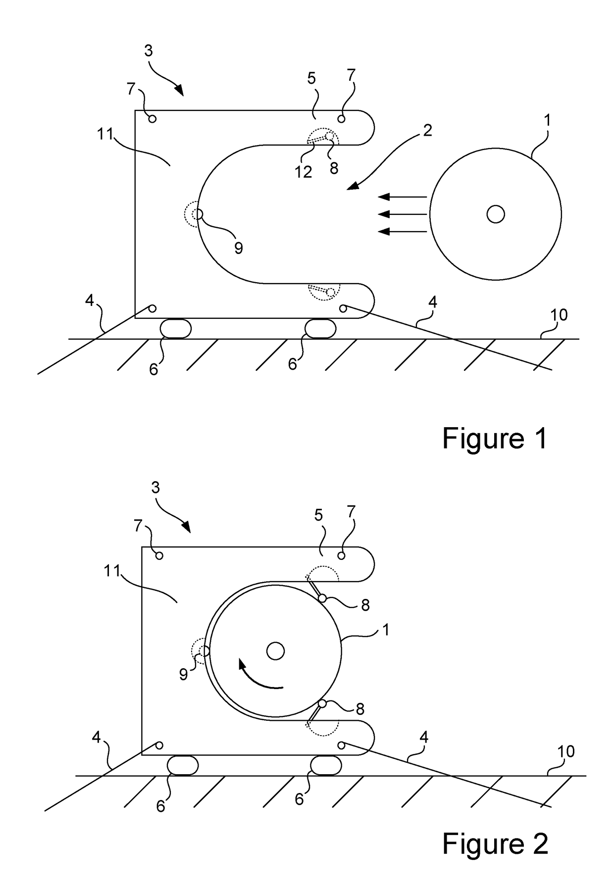
[0043]Prior to loading or unloading a cable from a cable storage tank 1, the tank needs to be positioned in the loading bay area 2 of the cable loading structure 3 (see FIG. 1). This may be achieved by maneuvering the tank whilst the cable loading structure 3 is moored for example against a harbour wall, a quay, another vessel or at an anchorage. Equally, the cable loading structure 3 may be maneuvered into position whilst the tank is substantially stationary.

[0044]FIG. 1 shows a plan view of a tank 1 and a cable loading structure 3. In this example, the cable loading structure 3 is tied up alongside a quay 10. Initially, the tank is not engaged with the structure 3 but is being brought towards it to be received in the loading bay area 2.

[0045]The floating cable tank 1 may be pushed by tug (not shown) and / or pulled by lines (not shown) into the loading bay area 2 of the cable loading structure 3. The cable loading structure 3 is moored, via lines 4 from bollards 7, against the quays...


PUM


Abstract

The invention provides a floatable cable loading facility (3) for receiving and controlling a cable storage tank (1) which can be used without providing additional infrastructure on a quay or vessel. The cable loading facility is able to receive and retain a tank (1) while rotating it to allow loading and unloading of the cable.

Description

CROSS-REFERENCE TO RELATED APPLICATIONS[0001]The present application claims priority to PCT International Application No. PCT / GB2014 / 053685 filed on Dec. 12, 2014, which claims priority to GB1401169.6 filed Jan. 23, 2014, the entirety of the disclosures of which are expressly incorporated herein by reference.STATEMENT RE: FEDERALLY SPONSORED RESEARCH / DEVELOPMENT[0002]Not Applicable.FIELD OF THE INVENTION[0003]The invention relates to loading, storing, transporting and unloading elongate products (such as subsea cables, umbilicals and flexible flow lines) on to or off floating vessels or tanks.BACKGROUND OF THE INVENTION[0004]Elongate products such as subsea cables, umbilicals and flexible flow lines are typically rolled or coiled to reduce their overall dimensions for storage and transportation.[0005]For instance, they are often loaded into a storage tank or reel which is rotated to receive the linearly delivered product. Where the axis of rotation is vertical the storage tank is ty...

Claims


Application Information

Patent Timeline
Patent Type & Authority Patents(United States)
IPC IPC(8): B63B35/04B63B27/36F16L1/20
CPCB63B35/04F16L1/203B63B27/36B63B35/03B65H75/40F16L1/20
Inventor YOUNG, JAMESWARD, PHILIPFEATHERSTONE, JEREMY
Owner JDR CABLE SYST
Why Eureka
Try Eureka