Barrel clamp

a barrel and clamping technology, applied in the field of barrel clamping, can solve the problems of dissipating unburnt explosive residue before they can produce muzzle flashes, disrupting the mixture of firing gasses, etc., and achieves the effects of dissipating unburnt explosive residue, dissipating combustible by-products, and easy installation

Inactive Publication Date: 2019-01-01
EMPTY SHELL LLC
View PDF6 Cites 2 Cited by
  • Summary
  • Abstract
  • Description
  • Claims
  • Application Information

AI Technical Summary

Benefits of technology

[0007]In view of the foregoing disadvantages inherent in the known types of barrel clamps and muzzle flash suppression devices, a barrel clamp for a multi-barreled firearm, such as for an M-134, may direct fresh air into proximity of firing barrels, thereby disrupting the mixture of firing gasses and dissipating unburnt explosive residue before they can produce muzzle flash. Such a barrel clamp should be easily installed and effective as a barrel clamp on existing and newly developed platforms, effective in the dissipation of combustible by-products which contribute to muzzle flash, intuitive in use and operation, and robust in construction.
[0008]To accomplish these objectives, the barrel clamp may comprise a brace plate with a central support tube extending therefrom. A muzzle housing may reside at an end of the support tube opposite the base plate, surrounding the muzzle ends of the multiple barrels of the firearm. The barrel housing may feature at least one vane, which may serve to direct ambient, fresh air directly onto one or more muzzles and associated barrels. By directing fresh air inwards and onto the barrels, the barrel clamp would directly contribute to both the cooling of the barrels and to the dispelling of left over explosive gasses from firing each round of ammunition. This, in turn, would reduce muzzle flash and allow for more rapid rates of fire. Ideally, there could be at least one vane for each barrel as this would evenly distribute fresh air for the cooling effect of the barrel clamp.

Problems solved by technology

In view of the foregoing disadvantages inherent in the known types of barrel clamps and muzzle flash suppression devices, a barrel clamp for a multi-barreled firearm, such as for an M-134, may direct fresh air into proximity of firing barrels, thereby disrupting the mixture of firing gasses and dissipating unburnt explosive residue before they can produce muzzle flash.

Method used


Image

  • Barrel clamp
  • Barrel clamp
  • Barrel clamp

Examples


Embodiment Construction

[0023]With reference now to the drawings, the preferred embodiment of the barrel clamp is herein described. It should be noted that the articles “a”, “an”, and “the”, as used in this specification, include plural referents unless the content clearly dictates otherwise.

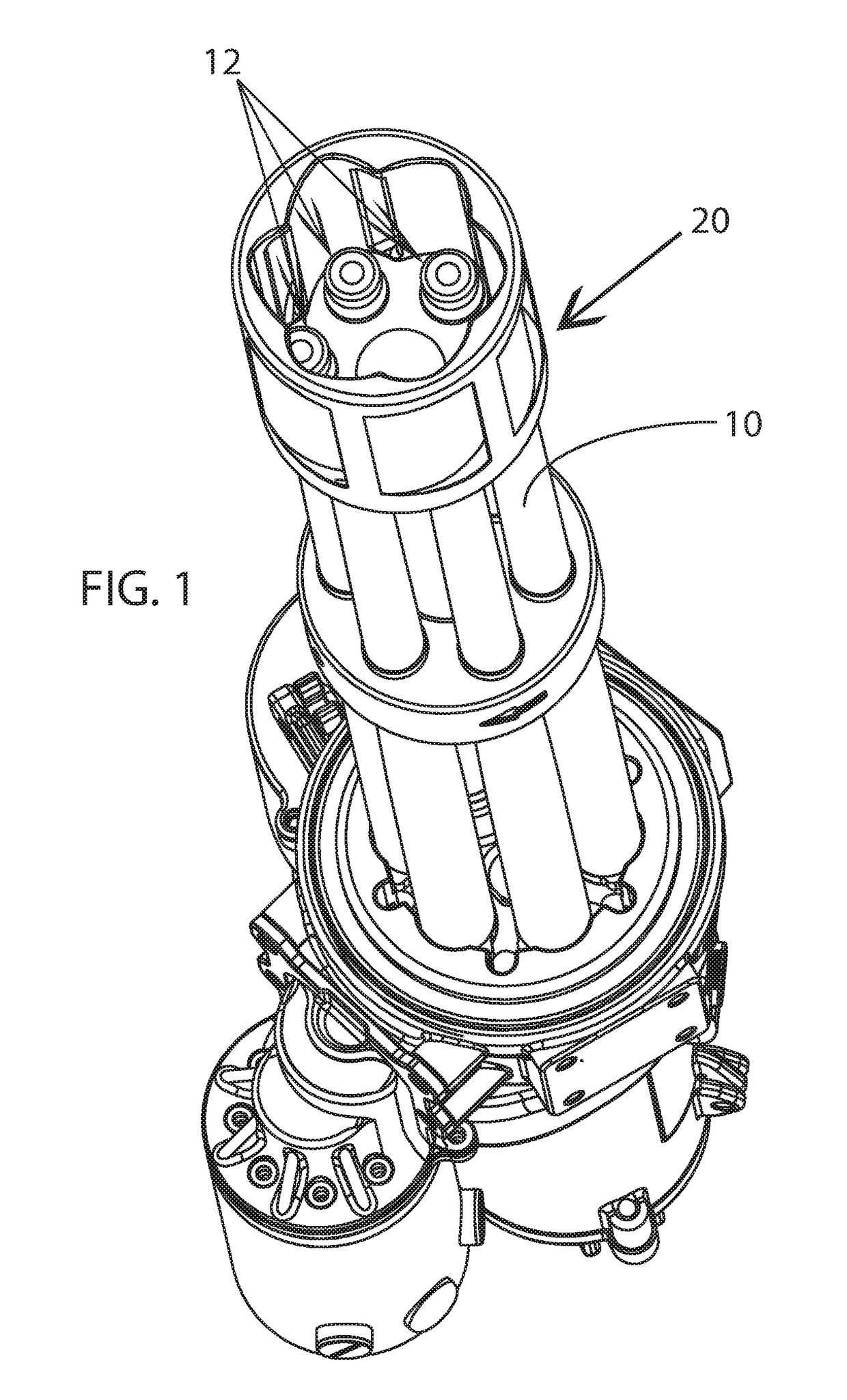
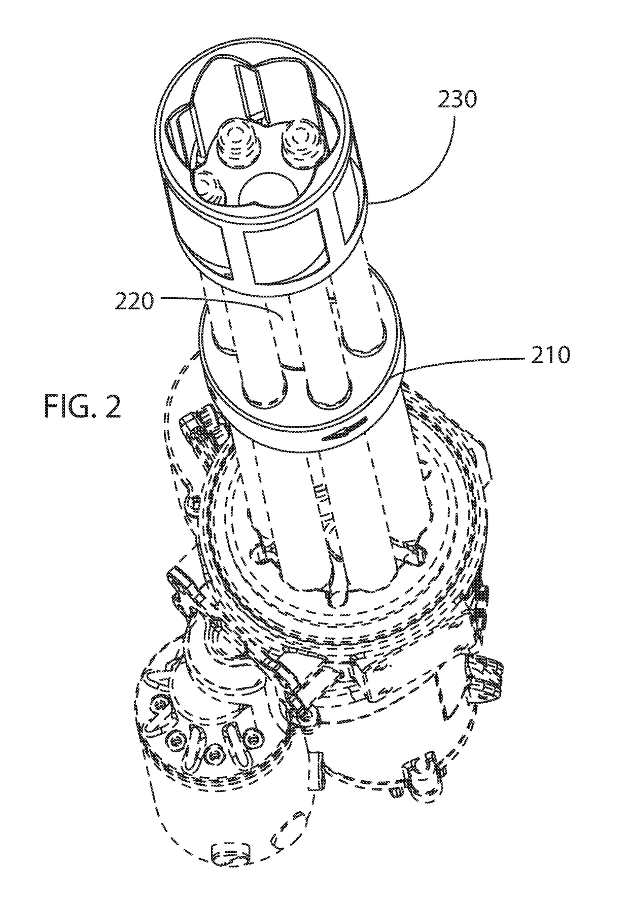
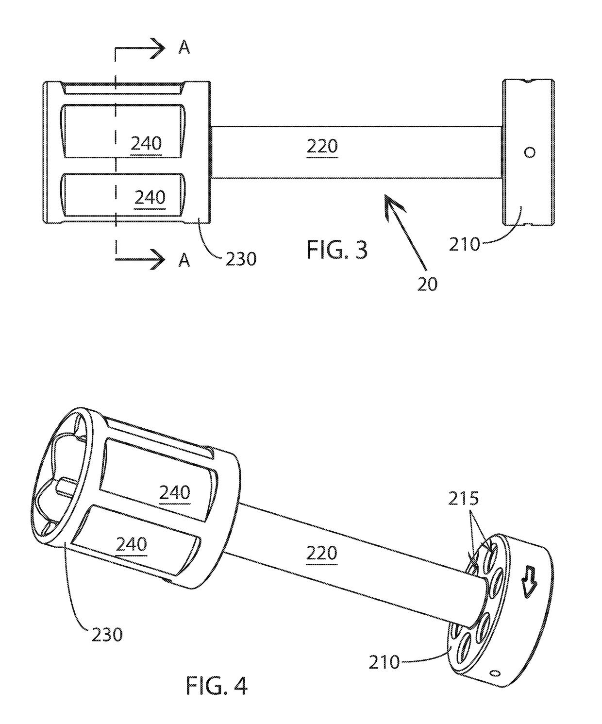
[0024]With reference to FIGS. 1 and 2, the barrel clamp 20 is a part of a comprehensive rotating, multi-barrel weapon system that directly supports barrels 10 at two locations along their length, near muzzles 12 and at some point further along the length of the barrel 10 as determined by the manufacturer. As seen in FIGS. 3 and 4, the barrel clamp is a simple construction. It features a base plate 210 at one end of a support tube 220 and a muzzle housing 230 at the support tube's opposite end. The base plate 210 and muzzle housing 230 each feature paired holes 215, 235, one of each pair being located on the muzzle housing 230 and one located on the base plate 210, through which the barrels 10 extend (FIGS. 5 and 6). Th...


PUM


Abstract

A barrel clamp for a Gatling-style firearm, or “mini-gun,” provides vanes for the direction of fresh air currents into the muzzle area of the firearm. The directed air streams contribute to cooling the barrels while in the firing cycle and also towards the disruption of fuel-rich gasses which contribute to muzzle flash.

Description

FIELD OF THE INVENTION[0001]The present invention relates to the field of firearms and more particularly relates to a barrel clamp for a multiple barreled rotary firearm.BACKGROUND OF THE INVENTION[0002]The modern “mini-gun,” or M-134, can trace its origins to the original Gatling gun of the mid-nineteenth century. It is a machine gun which fires projectiles in an automatic fashion. In the process of firing these projectiles, the gun utilizes a plurality of barrels (usually six) which consecutively rotate in a circular circuit into a single position which allows for the firing of a projectile. Each barrel, then, is only used to fire one-sixth of the projectiles, spending the remaining time cooling in an air current caused by the rotation of the barrels. Over time, many improvements have been made to the original Gatling gun, resulting in the modern M-134. However, each variant of the M-134 has always featured the rotatable barrels which are the signature characteristic of this famil...

Claims


Application Information

Patent Timeline
Patent Type & Authority Patents(United States)
IPC IPC(8): F41F1/10F41A21/08F41A21/34F41A21/24F41A21/48
CPCF41A21/34F41A21/08F41F1/10F41A21/487F41A21/24
Inventor ABBOTT, BRIAN F.
Owner EMPTY SHELL LLC
Why Eureka
Try Eureka