Control of networked lighting devices

a lighting device and network technology, applied in the direction of data switching networks, instruments, wireless communication, etc., can solve the problems of affecting the user experience, and the current lighting control network system may not be able to guarantee the synchronization of the control of the device, so as to achieve different network impact, lower network impact, and higher impa

Inactive Publication Date: 2019-01-01
SIGNIFY HLDG BV
View PDF14 Cites 1 Cited by
  • Summary
  • Abstract
  • Description
  • Claims
  • Application Information

AI Technical Summary

Benefits of technology

[0010]The control device makes a trade-off between maximizing synchronicity and minimizing delay between the user input and the execution of the input by generating messages based on their impact on the network. Occasionally varying between the generation of the plurality of messages of a first type and the single second message of a second type, while considering their impact on the network, may result in an optimized user experience. The control device provides the advantage that it is able to utilize the network optimally by generating messages based on their impact on the network.
[0016]In an embodiment the control device further comprises a user interface arranged for receiving the user input. The processor may be further arranged for processing the user input received from the user via the user interface. The user input may for example comprise adjusting a control parameter of the plurality of lighting devices (for example the colour of the plurality of lighting devices). The user input may comprise selecting the plurality of lighting devices. The user input may further comprise grouping and / or ungrouping of the plurality of lighting devices. The user interface may comprise a touch-sensitive device such as a touchpad or a touchscreen, an audio sensor such as a microphone, a motion sensor such as an accelerometer and / or a gyroscope for detecting movement and / or one or more buttons for receiving the user input. An advantage of comprising a user interface in the control device is that it may receive the user input directly, which may improve the speed of controlling the plurality of lighting devices.

Problems solved by technology

When groups of lighting devices are controlled, current lighting control network systems may not be able to guarantee synchronized control of these devices mainly because these devices are controlled via individual control commands.
Group control commands may guarantee synchronicity, although they often have a bigger impact on the network and may therefore be prone to delaying the execution of the commands due to the limited network capability.
These problems have a negative effect on the usability of the system and may result in a negative user experience.
This imposed location-based architecture reduces the amount of transmitted data required to control the lighting devices and, thus, reduces the radio bandwidth required to control the lighting devices.

Method used


Image

  • Control of networked lighting devices
  • Control of networked lighting devices
  • Control of networked lighting devices

Examples


Embodiment Construction

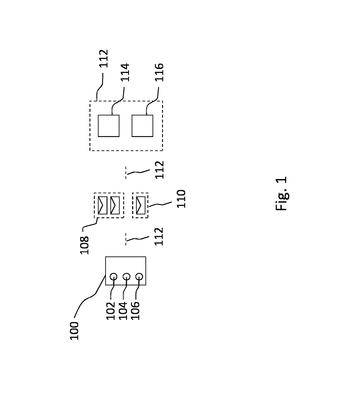
[0030]FIG. 1 schematically shows an embodiment of a control device 100 for controlling a plurality of lighting devices 114, 116 via a network 112. The control device 100 comprises a receiver 102 for receiving a signal based on a user input related to adjusting a control parameter of the plurality of lighting devices 114, 116, a processor 104 for generating, based on the received signal and on a predetermined network capacity, one of: a plurality of messages of a first type 108 and a single message of a second type 110, and a transmitter 106 for transmitting the generated plurality of messages of a first type 108 or the single message of a second type 110 via the network 112, thereby adjusting the control parameter of the plurality of lighting devices 114, 116. The plurality of lighting devices 114, 116 and the control device 100 are connected via a wireless network 112 (e.g. a mesh structured network). The plurality of lighting devices 114, 116 may be a group of any type of lighting...


PUM


Abstract

A control device for controlling a plurality of lighting devices via a network is disclosed. The control device 100 comprises a receiver (102) for receiving a signal based on a user input related to adjusting a control parameter of the plurality of lighting devices (114, 116). The control device further comprises a processor (104) for generating, based on the received signal, on a predetermined network capacity and on the number of user input commands received within a predetermined time period, one of: a plurality of messages of a first type (108) and a single message of a second type (110). The control device further comprises a transmitter (106) for transmitting the generated plurality of messages of a first type (108) or the single message of a second type (110) via the network (112), thereby adjusting the control parameter of the plurality of lighting devices (114, 116). The control device is able to utilize the network optimally by generating messages based on their impact on the network. This may improve the control of the plurality of lighting devices and provide an optimized user experience.

Description

CROSS-REFERENCE TO PRIOR APPLICATIONS[0001]This application is the U.S. National Phase application under 35 U.S.C. § 371 of International Application No. PCT / EP2015 / 070959, filed on Sep. 14, 2015, which claims the benefit of European Patent Application No. 14186304.3, filed on Sep. 25, 2014. These applications are hereby incorporated by reference herein.FIELD OF THE INVENTION[0002]The invention relates to a control device for controlling a plurality of lighting devices.BACKGROUND[0003]Future and current home and professional environments will contain a large number of controllable lighting devices for creation of ambient, atmosphere, accent or task lighting. These controllable lighting devices are often connected and controlled via a (wireless) network. These lighting devices can be controlled individually or in groups via a user interface of a smart device (e.g. a smartphone or a tablet pc). When groups of lighting devices are controlled, current lighting control network systems ma...

Claims


Application Information

Patent Timeline
Patent Type & Authority Patents(United States)
IPC IPC(8): H05B37/02H05B33/08H04L12/00H04W88/06H04L12/28H05B44/00
CPCH05B37/0272H04L12/00H04L12/282H05B37/0281H04W88/06H05B33/0815H05B37/029H04L12/2807H04L2012/285H04L12/2832H05B47/19G08C17/02G08C2201/42G08C2201/31G08C2201/93H05B47/16H05B47/155
Inventor GOERGEN, DANIEL MARTIN
Owner SIGNIFY HLDG BV
Why Eureka
Try Eureka