Electrical switching system for a three-phase network
Active Publication Date: 2019-01-08
MASCHFAB REINHAUSEN GEBR SCHEUBECK GMBH & CO KG
View PDF11 Cites 0 Cited by
Summary
Abstract
Description
Claims
Application Information
AI Technical Summary
This helps you quickly interpret patents by identifying the three key elements:
Problems solved by technology
Method used
Benefits of technology
Benefits of technology
The invention provides an electrical system that is cheaper, space-saving, and easy to operate. The switching assembly is easy to install and maintain, and has a compact construction. The method for operating the switching assembly allows for safe, low-maintenance, and efficient change-over switching. Overall, this system offers savings in material, oil, and complexity of cable routing and switching.
Problems solved by technology
Due to the numerous contacts, such switching means have a complex and elaborate structure so that it presents a great challenge to put them into service properly.
Furthermore, it is not only costly, but also complicated to control and operate the respective switching means separately.
In addition, the installation of individual switching means takes up a particularly large amount of space in the individual transformers, making them to large for regular transport.
This star-point rotary off-circuit tap-changer, which serves for load-free change-over switching between winding taps, is not suited as “Advanced Retard Switch”.
Method used
Image
Click on the blue label to locate the original text in one second.
Reading with bidirectional positioning of images and text.
Examples
first embodiment
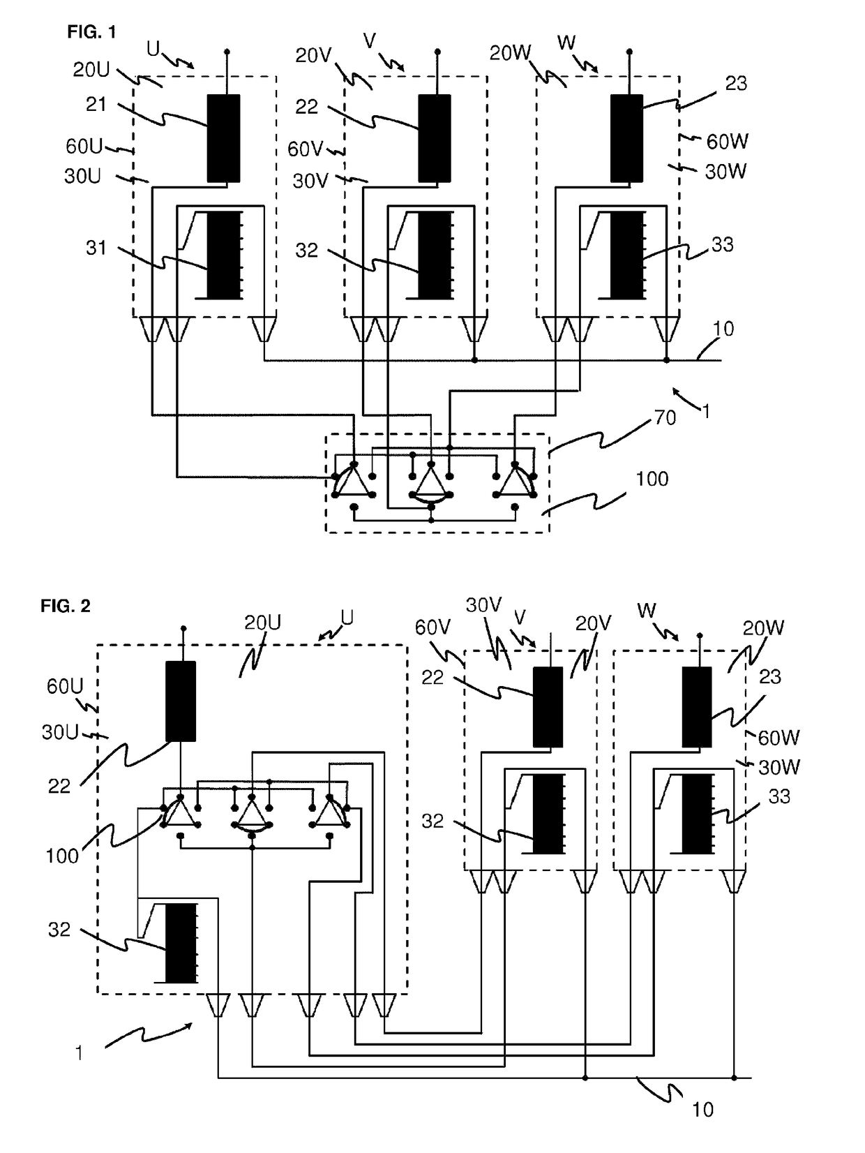
[0101]Schematically illustrated in FIG. 1 is an electrical system 1 for a three-phase alternating current network.
[0102]In this embodiment, the electrical system 1 comprises a switching assembly 100, a transformer 20U, 20V, 20W for each phase U, V, W of the alternating current network, and a separate transformer housing 60U, 60V, 60W for each transformer 20U, 20V, 20W. The primary sides 30U, 30V, 30W assigned to the phases U, V, W each comprise a main winding 21, 22, 23 and a regulating winding 31, 32, 33. By means of the switching assembly 100, the main windings 21, 22, 23 can each be individually connected in series with a regulating winding 31, 32, 33. Each regulating winding 31, 32, 33 has taps that can be switched by an on-load tap changer that is not illustrated here. A preselector, which is not illustrated here, can be arranged between each main winding 21, 22, 23 and each regulating winding 31, 32, 33. This preselector can be used for selectively adding or subtracting the re...
second embodiment
[0123]The main windings 21, 22, 23 and the regulating windings 31, 32, 33 of three transformers and the switching assembly 100 are schematically illustrated in different switching phases in FIGS. 8, 9, 10, 11, and 12.
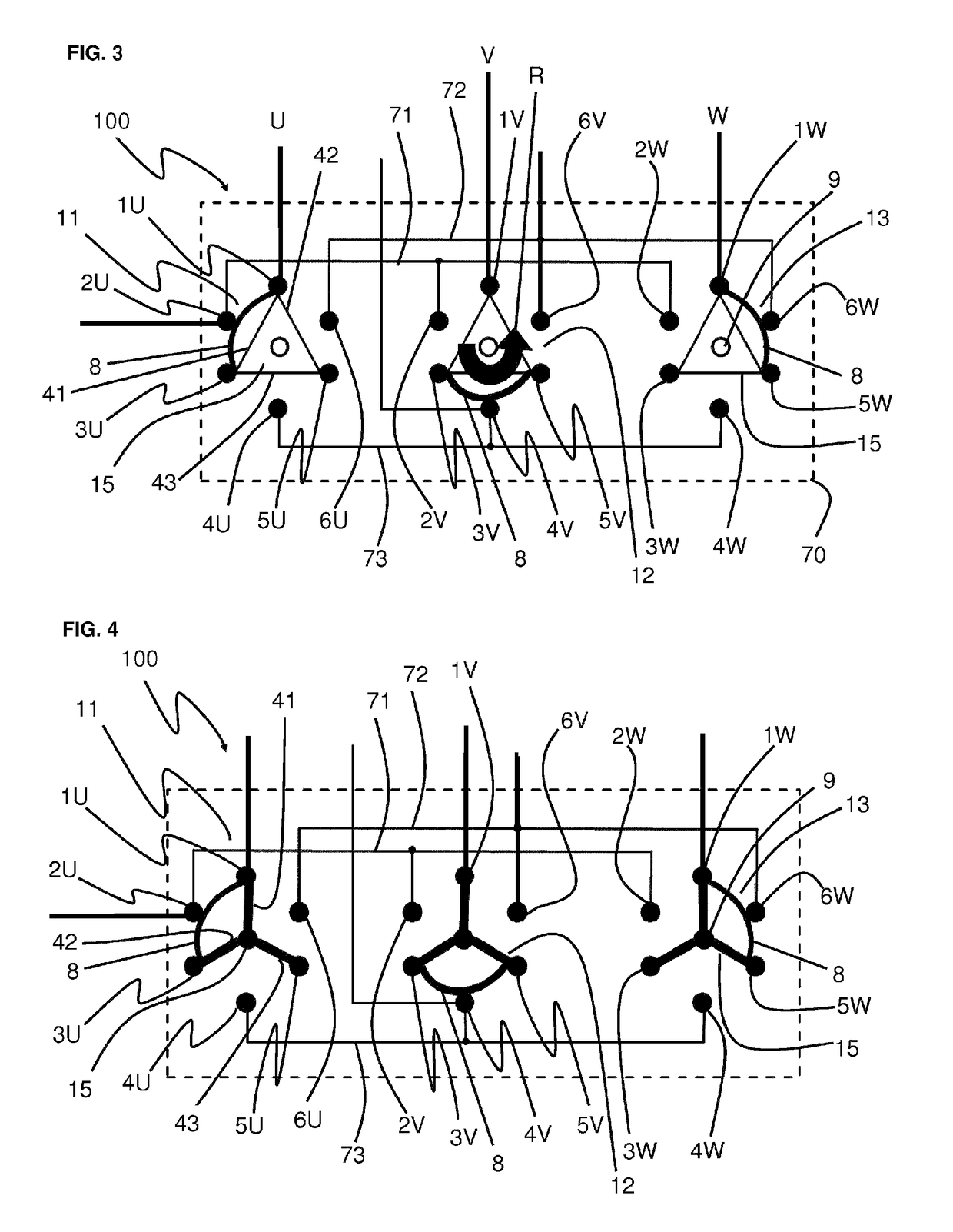
[0124]FIG. 8 shows the switching assembly 100 in a first stationary state. By the switching assembly 100, it is intended to selectively switch a first main winding 21 of the first phase U, a second main winding 22 of the second phase V, and a third main winding 23 of the third phase W to a first regulating winding 31, a second regulating winding 32, and a third regulating winding 33. The regulating windings 31, 32, 33 are electrically conductively connected with a star point 10. As already mentioned above, each regulating winding 31, 32, 33 can be formed as a coarse winding or as a regulating winding.
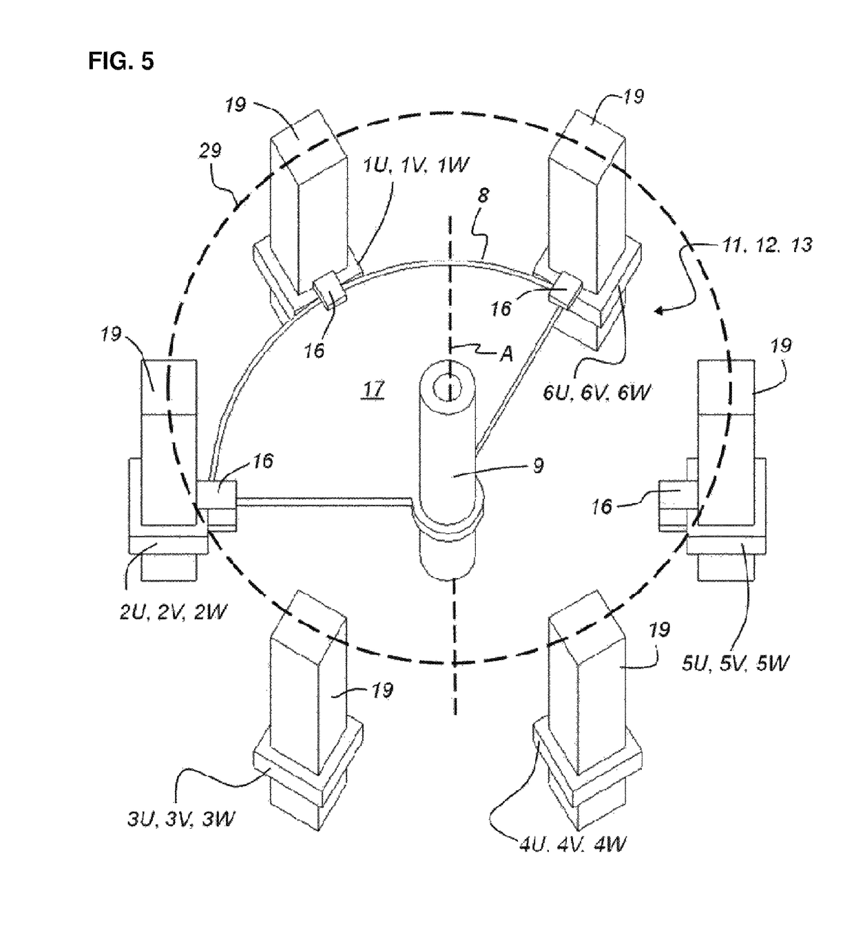
[0125]Each of the three subassemblies 11, 12, 13 has a selector bridge 15 (see FIG. 6, 7) that, via the first arm 41 of the selector bridge 15 with the first main winding ...
PUM
Abstract
An electrical system (1) for a three-phase alternating current network, comprisinga transformer (20U, 20V, 20W) with a primary side (30U, 30V, 30W) and a secondary side for each phase (U, V, W) of the alternating current network;a separate transformer housing (60U, 60V, 60W) for each transformer (20U . . . W); anda switching assembly (100) connected to the transformers (20U . . . W);whereinthe primary side (30U . . . W) and / or the secondary side has a main winding (21, 22, 23) and a regulating winding (31, 32, 33) in each phase;the switching assembly (100) is designed such that it can connect each regulating winding (31, 32, 33) with each of the main windings (21, 22, 23); andthe switching assembly (100) is arranged in one of the transformer housings (60U . . . W) or in an own switch housing (70).
Description
CROSS REFERENCE TO RELATED APPLICATIONS[0001]This application is the US-national stage of PCT application PCT / EP2014 / 076383 filed 3 Dec. 2014 and claiming the priority of German patent application 102013113505.6 itself filed 5 Dec. 2013 and German patent application 102014107795.4 itself filed 3 Jun. 2014.FIELD OF THE INVENTION[0002]The invention relates to an electrical system for a three-phase alternating current network, to a switching assembly for using in such an electrical system, and to a method for operating a switching assembly.BACKGROUND OF THE INVENTION[0003]DE 20 2011 005 058 describes a transformer with a switching device. This transformer comprises a three-phase primary winding, a three-phase first secondary winding and a three-phase second secondary winding with tap adjustment. Each secondary winding has a group of three individual windings. Provided in this context are three independent switching means, by which the groups of individual windings of the first and the ...
Claims
Application Information
Patent Timeline
Application Date:The date an application was filed.
Publication Date:The date a patent or application was officially published.
First Publication Date:The earliest publication date of a patent with the same application number.
Issue Date:Publication date of the patent grant document.
PCT Entry Date:The Entry date of PCT National Phase.
Estimated Expiry Date:The statutory expiry date of a patent right according to the Patent Law, and it is the longest term of protection that the patent right can achieve without the termination of the patent right due to other reasons(Term extension factor has been taken into account ).
Invalid Date:Actual expiry date is based on effective date or publication date of legal transaction data of invalid patent.

