
Automotive battery mounting structure

a technology for mounting structures and automobile batteries, which is applied to battery mounting, cell components, jet propulsion, etc., can solve the problems of affecting the safety of passengers, and the automotive battery in the related art may not be stably secured, so as to improve the crashworthiness

Active Publication Date: 2019-01-08
HYUNDAI MOTOR CO LTD +1
View PDF7 Cites 11 Cited by
  • Summary
  • Abstract
  • Description
  • Claims
  • Application Information

AI Technical Summary

Benefits of technology

The patent is about a way to mount a car's battery on a side frame of a vehicle to meet safety regulations and make the vehicle safer in a crash. The invention provides a stable mounting structure for the battery on the side frame.

Problems solved by technology

However, in the case of a collision of the vehicle, the leg brackets may easily collapse so that the automotive battery may directly hit a booster while moving to a lower side of the vehicle.
At the present time, the booster may be pushed toward the internal of the vehicle to move pedals toward the internal, and the pedals may cause an injury to a lower limb of a driver or passenger.
Furthermore, the automotive battery in the related art may not be stably secured to the battery tray and thus may be easily damaged or separated from the battery tray in the case of a collision of the vehicle.
Thus, the automotive battery in the related art may not meet the requirements of crash-regulations in China, Europe, and the like.

Method used


Image

  • Automotive battery mounting structure
  • Automotive battery mounting structure
  • Automotive battery mounting structure

Examples


Embodiment Construction

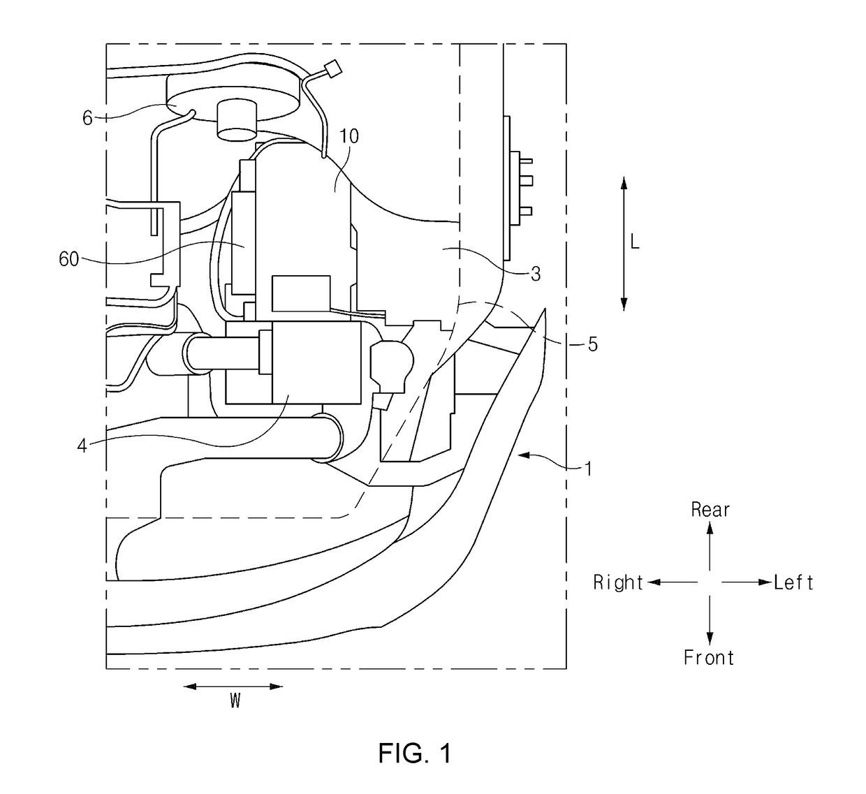
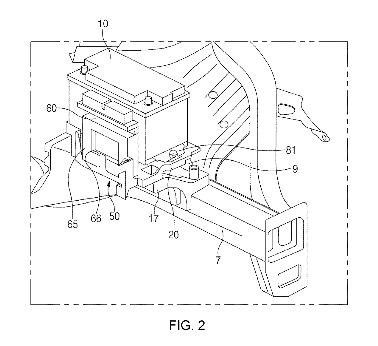
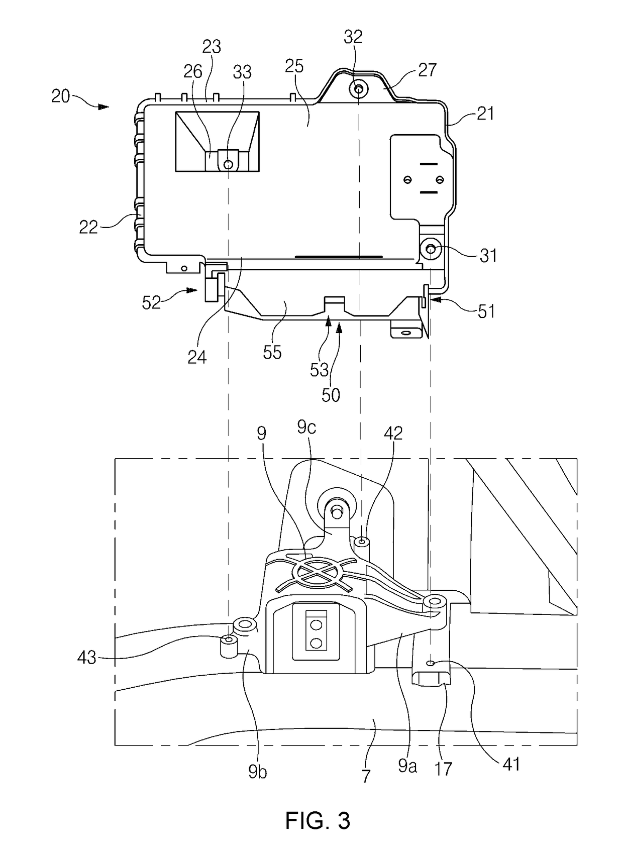
[0062]Reference will now be made in detail to various embodiments of the present invention(s), examples of which are illustrated in the accompanying drawings and described below. While the invention(s) will be described in conjunction with exemplary embodiments, it will be understood that the present description is not intended to limit the invention(s) to those exemplary embodiments. On the contrary, the invention(s) is / are intended to cover not only the exemplary embodiments, but also various alternatives, modifications, equivalents and other embodiments, which may be included within the spirit and scope of the invention as defined by the appended claims.

[0063]Terms including “first”, “second”, “A”, “B”, “(a)”, “(b)”, and the like, may be used herein to describe elements of the present invention. Such terms are only used to distinguish one element from another element, and the substance, sequence, order, or number of these elements is not limited by these terms. Unless otherwise d...


PUM

PropertyMeasurementUnit
electrical energyaaaaaaaaaa
gravityaaaaaaaaaa
weightaaaaaaaaaa

Abstract

An automotive battery mounting structure may include a battery tray connected to one of a pair of front side members disposed on a lower side of an engine compartment, and a battery secured to the battery tray. A transmission mount and a leg bracket may be coupled to the front side member, and the battery tray may be coupled to the transmission mount and the leg bracket by a plurality of fasteners.

Description

CROSS-REFERENCE TO RELATED APPLICATION[0001]The present application claims priority to Korean Patent Application No. 10-2017-0076656, filed on Jun. 16, 2017, the entire contents of which is incorporated herein for all purposes by this reference.BACKGROUND OF THE INVENTIONField of the Invention[0002]The present invention relates to an automotive battery mounting structure that enables an automotive battery to be stably mounted, meeting the requirements of crash-regulations and improving crashworthiness.Description of Related Art[0003]A vehicle needs an electrical energy supply that may supply electrical energy to start an engine or to operate auxiliary components and devices. While the engine of the vehicle is running, an alternator operated by the engine supplies electrical energy, whereas while the engine is not running, an automotive battery supplies electrical energy.[0004]The automotive battery is mounted in an engine compartment to meet the requirements of crash-regulations in ...

Claims


Application Information

Patent Timeline
Patent Type & Authority Patents(United States)
IPC IPC(8): B60K1/04H01M2/10B60R16/04H01M50/249H01M50/262
CPCH01M2/1083B60R16/04H01M2220/20H01M50/262H01M50/249Y02E60/10B60K5/12B60Y2304/07
Inventor YANG, SENG JOOJUNG, DO GEUNYANG, HEE GUNPARK, JI WOONGCHOI, SEOG WONKIM, SEUNG WON
Owner HYUNDAI MOTOR CO LTD
Learn More