Wheelchair backrest mounting system

a backrest and mounting system technology, applied in the field of wheelchair backrest mounting systems, can solve the problems of affecting the freedom of movement, adding extra weight, and causing reliance, and achieves the effects of reducing reliance, reducing interference between canes and users' arms, and facilitating movement and rotation

Active Publication Date: 2019-01-22
SUNRISE MEDICAL (US) LLC
View PDF24 Cites 14 Cited by
  • Summary
  • Abstract
  • Description
  • Claims
  • Application Information

AI Technical Summary

Benefits of technology

[0004]This invention relates to wheelchair seatback mounting systems. This mounting system eliminates reliance on traditional backrest canes on the sides of the wheelchair to mount and support a backrest. This eliminates the interference between the canes and user's arms, particularly during propulsion, allowing greater freedom of body (trunk) movement and rotation. Since the backrest mounts are located in the center of the shell, the backrest width is not dependent on wheelchair width and can be smaller or larger than wheelchair. Mounting hardware is located in the center of the back shell and allows adjustment for different height and angular backrest positions.
[0005]Two pivoting axes allow additional height, depth and angle adjustment. This can be an infinite adjustment or incremental with gear / teeth feature on the offset mounts. Two offset mounts are inter-locked with a locking tube and screw connection to eliminate any misalignment in the backrest tubes.

Problems solved by technology

Many known seating systems provide a variety of adjustments but are either bulky or cumbersome to adjust so that the seated user is comfortable.
This adds extra weight and an obstacle for freedom of movement, particularly in light weight or sport wheelchairs.

Method used


Image

  • Wheelchair backrest mounting system
  • Wheelchair backrest mounting system
  • Wheelchair backrest mounting system

Examples


Embodiment Construction

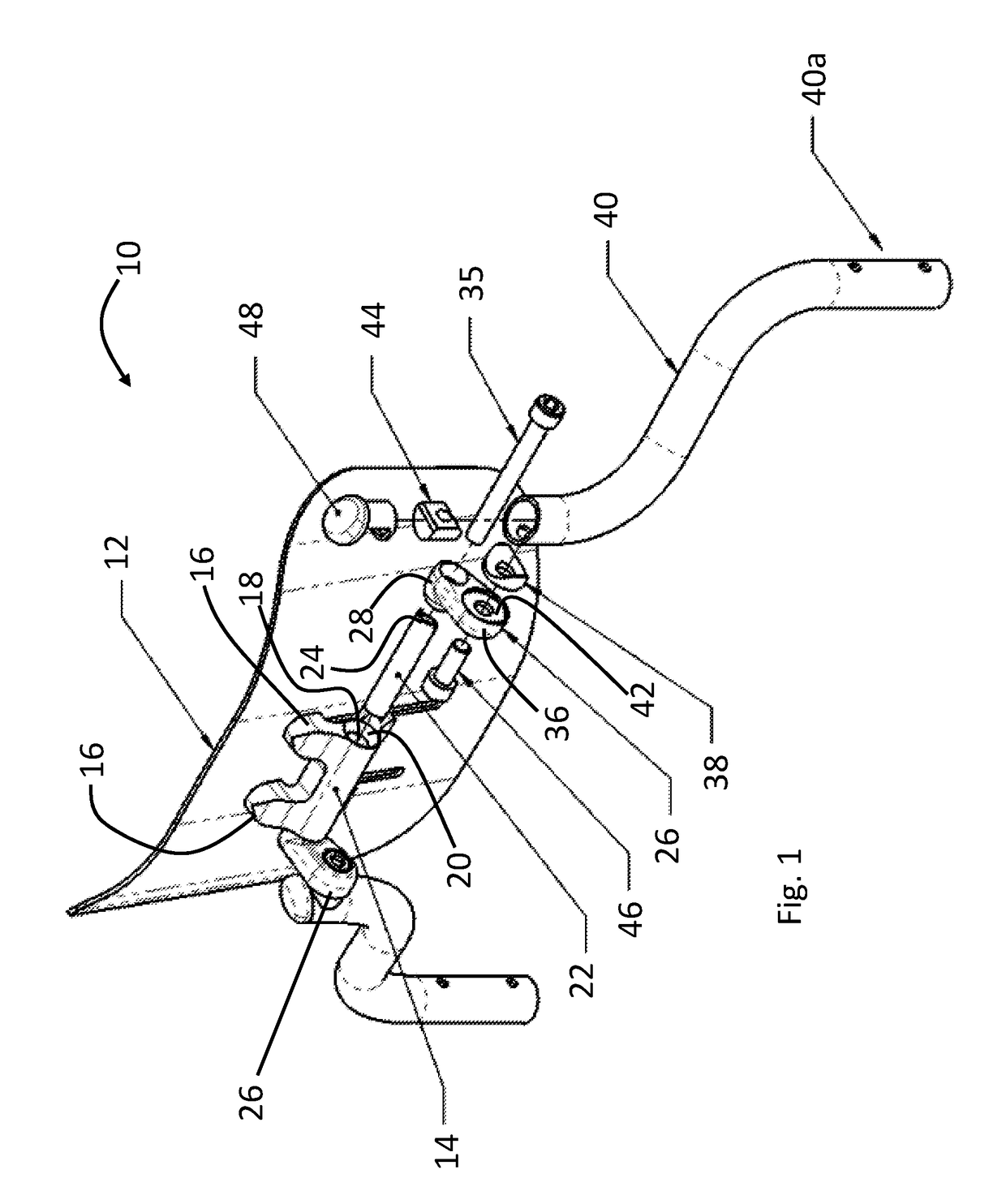
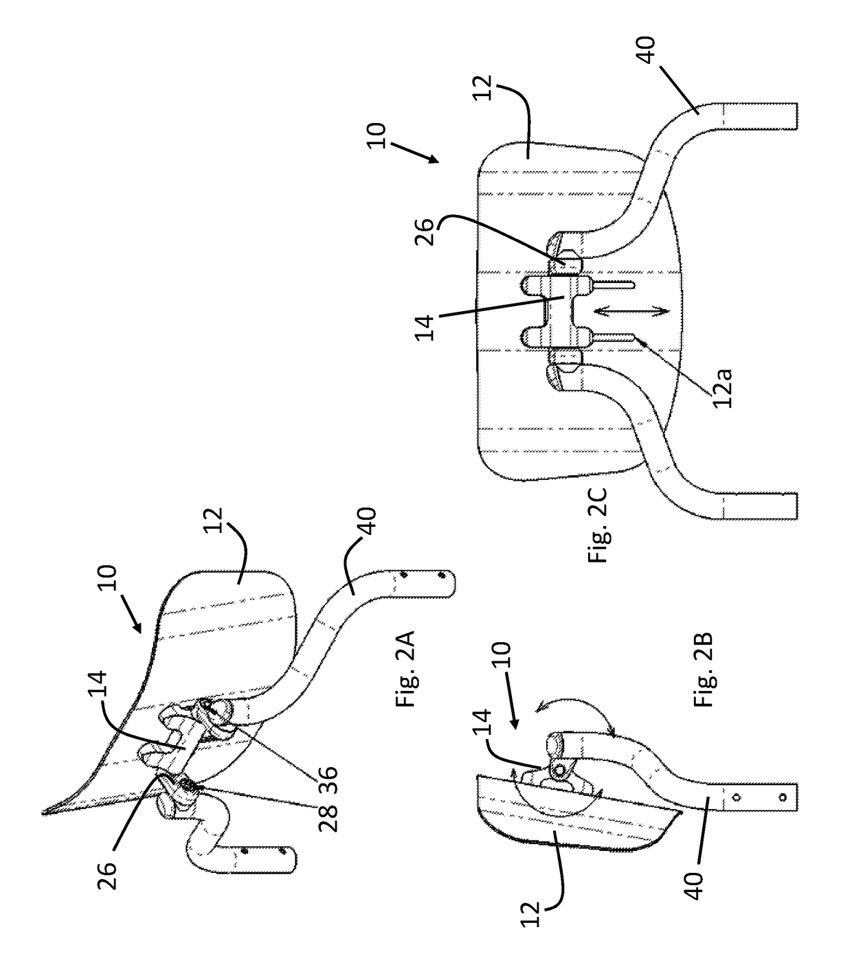
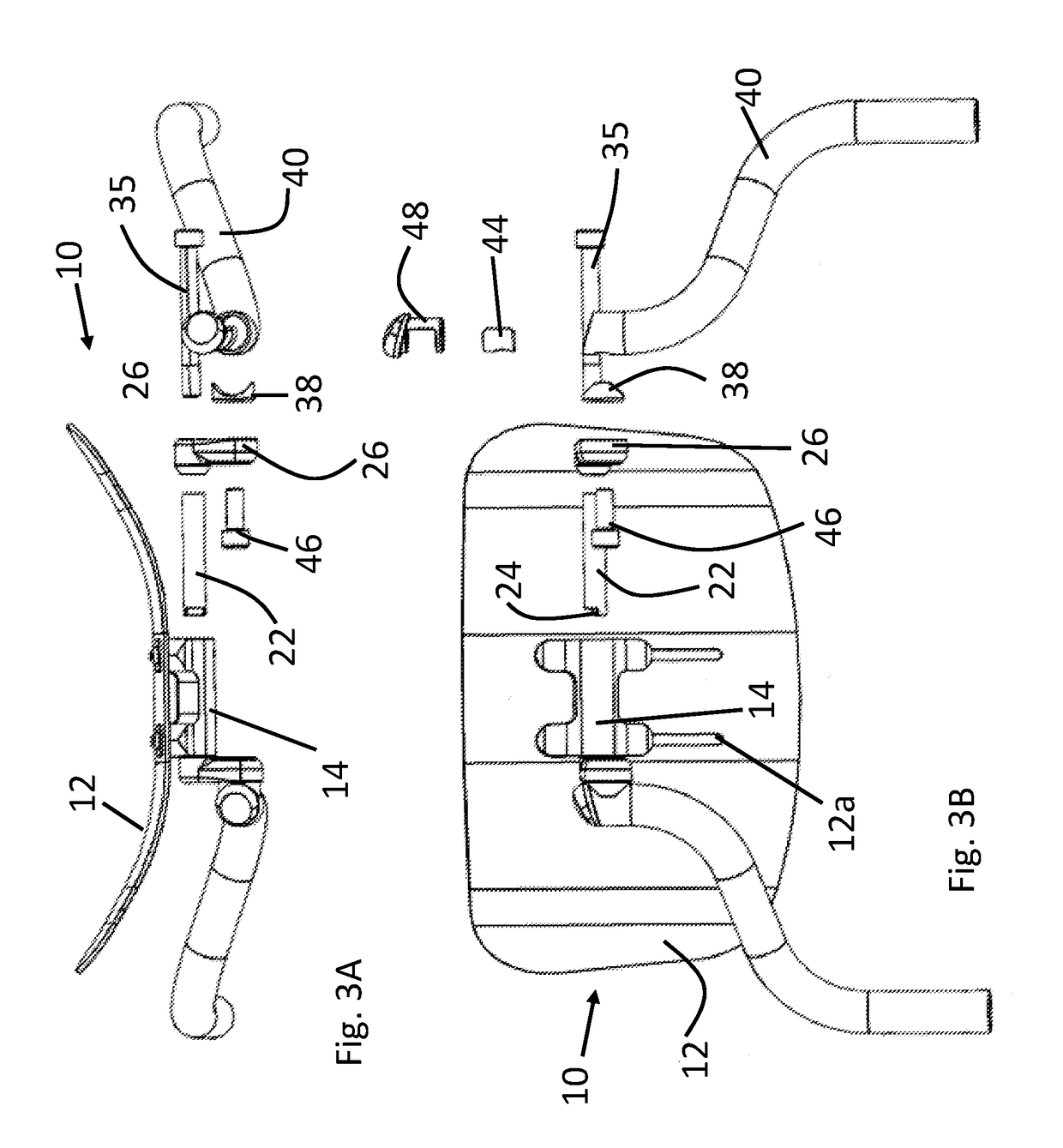
[0014]Referring now to the drawings, there is illustrated in FIG. 1 a wheelchair backrest mounting system, shown generally at 10. The backrest mounting system 10 attaches a backrest shell 12 to a wheelchair frame (shown at FIG. 6). The backrest mounting system 10 includes a mounting block 14 that is fastened to the backrest shell 12 by attachment pads 16. The mounting block 14 includes a bore 18 that extends therethrough and includes tapered or beveled receivers 20. An offset locking tube 22 is configured to extend through and be supported by the bore 18 for rotation. The offset locking tube 22 terminates in locking teeth 24. The illustrated locking teeth 24 are shown as tube end cutouts that have offset profiles along the tube longitudinal axis. Other tooth arrangements, such as multiple teeth, may be provided if desired. The locking tube 22 maintains spaced-apart offset mounts 26 oriented in alignment relative to each other. The offset mounts 26 include pivot ends 28, as shown in ...


PUM


Abstract

A backrest mounting system provides angular and height adjustment of a backrest shell independent of backrest canes. The backrest mounting system attaches to a centrally located mounting structure on the backrest shell and defines at least two pivot axes that determine the angular position of the backrest shell relative to a wheelchair seat.

Description

CROSS-REFERENCE TO RELATED APPLICATIONS[0001]This application claims the benefit of U.S. Provisional Application No. 62 / 247,540, filed Oct. 28, 2015, the disclosure of which is incorporated herein by reference.BACKGROUND OF THE INVENTION[0002]This invention relates in general to wheelchair seating systems and, in particular, to an angle adjustable backrest mounting system.[0003]Wheelchairs are typically intended to be used by persons having different size, physical constitutions, and impairments. These conditions are accommodated, in one respect, by providing adjustable seating systems that permit the seat and / or seat back to be positioned to the user's seated body contours. Many known seating systems provide a variety of adjustments but are either bulky or cumbersome to adjust so that the seated user is comfortable. In addition, many adjustable seating systems for manual wheelchairs rely on backrest canes as part of the backrest mounting structure. This adds extra weight and an obs...

Claims


Application Information

Patent Timeline
Patent Type & Authority Patents(United States)
IPC IPC(8): A47C1/024A61G5/10A47C7/44A47C7/40A61G5/02A61G5/12
CPCA61G5/122A61G5/1067
Inventor TSUBER, VASILY G.
Owner SUNRISE MEDICAL (US) LLC
Why Eureka
Try Eureka