Method and system for ladar pulse deconfliction using delay code selection

Active Publication Date: 2019-01-22
AEYE INC
View PDF109 Cites 49 Cited by
  • Summary
  • Abstract
  • Description
  • Claims
  • Application Information

AI Technical Summary

Benefits of technology

[0006]As a solution to this technical challenge, the inventors disclose that the ladar transmitters can be designed to encode their own ladar pulses via a delay between successive ladar pulses. Thus, different ladar transmitters can employ different delays between successive ladar pulses to allow ladar receivers to distinguish between “own” ladar pulses and “interfering” ladar pulses. Preferably, these delays are fairly short time intervals and the number of pulses in the pulse sequence is kept low so as to keep the square root loss in effective energy low. Accordingly, the encoding can be referred to as a sparse burst code. For example, in an example embodiment, the pulse sequence can be a pulse pair (doublet) such that a single delay between pulses is used to distinguish “own” pulses from “interfering” pulses. In another example embodiment, the pulse sequence can be three pulses (triplet) such that two delays are used for encoding. In general, it should be understood that for a sequence of n pulses (n-tuple), there would be n−1 delays that can be used for encoding. Another benefit of the sparse burst code is that the number of samples needed to represent the pulses can be low, which contributes to computational efficiency and low latency processing.
[0021]Further still, the inventors disclose various optical data communication techniques that leverage the scanning ladar system to send and receive message data via encoded ladar pulses. Furthermore, laser dosage tracking as described herein can be employed to reduce the risks of overly exposing humans and cameras to excessive laser light.

Problems solved by technology

However, as ladar usage grows, particularly in fields such as automobile vision, the global presence of millions and potentially billions of ladar systems in the field poses a daunting technical challenge: how can the ladar systems be designed to differentiate their own ladar returns from those of other ladar systems?

Method used


Image

  • Method and system for ladar pulse deconfliction using delay code selection
  • Method and system for ladar pulse deconfliction using delay code selection
  • Method and system for ladar pulse deconfliction using delay code selection

Examples


Embodiment Construction

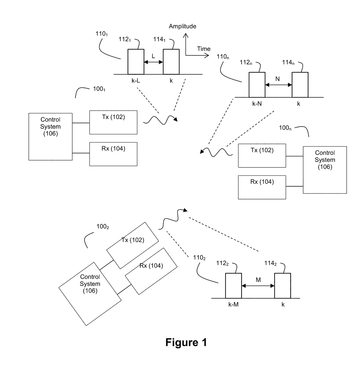
[0042]FIG. 1 depicts an example environment where there are multiple ladar systems 100 (e.g., 1001, 1002, . . . 100n) that transmit ladar pulses. Each ladar system 100 comprises a ladar transmitter 102, a ladar receiver 104, and a control system 106. Each ladar transmitter 102 is configured to generate and transmit ladar pulses into the environment. Each ladar receiver 104 is configured to receive and detect a light signal that may include ladar pulse reflections. As noted above, this received signal may also include noise such as interfering pulses / pulse reflections from other ladar systems. Each control system 106 can be configured to control how its corresponding ladar transmitter 102 and ladar receiver 104 operate. Examples of suitable ladar systems 100 are disclosed and described in greater detail in U.S. patent application Ser. No. 62 / 038,065, filed Aug. 15, 2014; and U.S. Pat. App. Pubs. 2016 / 0047895, 2016 / 0047896, 2016 / 0047897, 2016 / 0047898, 2016 / 0047899, 2016 / 0047903, 2016 / ...


PUM


Abstract

Disclosed herein are a number of example embodiments that employ controllable delays between successive ladar pulses in order to discriminate between “own” ladar pulse reflections and “interfering” ladar pulses reflections by a receiver. Example embodiments include designs where a sparse delay sum circuit is used at the receiver and where a funnel filter is used at the receiver. Also, disclosed are techniques for selecting codes to use for the controllable delays as well as techniques for identifying and tracking interfering ladar pulses and their corresponding delay codes. The use of a ladar system with pulse deconfliction is also disclosed as part of an optical data communication system.

Description

CROSS-REFERENCE AND PRIORITY CLAIM TO RELATED PATENT APPLICATIONS[0001]This patent application claims priority to provisional U.S. patent application Ser. No. 62 / 460,520, filed Feb. 17, 2017, and entitled “Method and System for Ladar Pulse Deconfliction”, the entire disclosure of which is incorporated herein by reference.[0002]This patent application is related to (1) U.S. patent application Ser. No. 15 / 896,219, filed this same day, and entitled “Ladar Pulse Deconfliction Method”, (2) U.S. patent application Ser. No. 15 / 896,233, filed this same day, and entitled “Ladar Pulse Deconfliction Apparatus”, (3) U.S. patent application Ser. No. 15 / 896,254, filed this same day, and entitled “Method and System for Ladar Pulse Deconfliction to Detect and Track Other Ladar Systems”, and (4) U.S. patent application Ser. No. 15 / 896,262, filed this same day, and entitled “Method and System for Optical Data Communication via Scanning Ladar”, the entire disclosures of each of which are incorporated ...

Claims


Application Information

Patent Timeline
Patent Type & Authority Patents(United States)
IPC IPC(8): G01C3/08G01S7/484G01S17/06G01S17/66G01S7/481G01S7/486G01S7/487G01S17/93G01S17/89G01S7/4861G01S7/4865G01S17/10G01S17/86G01S17/931
CPCG01S7/4861G01S7/484G01S7/487G01S7/4816G01S7/4865G01S7/4876G01S17/06G01S17/66G01S7/4873G01S17/936G01S17/89G01S17/10G01S7/006G01S2013/9316G01S17/86G01S17/931G01S7/4814G01S7/003H04B10/1123
Inventor DUSSAN, LUIS CARLOSSTEINHARDT, ALLAN
Owner AEYE INC
Why Eureka
Try Eureka