Ultrashort-pulse laser-working method and apparatus and structural bodies produced by using the same

a laser-working method and ultra-short-pulse technology, applied in the direction of optical elements, manufacturing tools, instruments, etc., can solve the problems of difficult and costly production of such masks, long working time, and low flexibility in terms of working shapes

Inactive Publication Date: 2006-07-04
RICOH KK
View PDF6 Cites 20 Cited by
  • Summary
  • Abstract
  • Description
  • Claims
  • Application Information

AI Technical Summary

Benefits of technology

[0021]When the laser beam is split by using the diffractive optical element, the number and the intensity distribution of the split laser beams can be changed in various manners depending upon the design of the diffractive optical element. Further, when the laser beam is split with the diffractive optical element, the ultrashort pulse laser beams can be irradiated upon the same location, while a very short time interval is being ensured among the irradiated beams.
[0029]By this, the worked shape can be controlled. Particularly, since the shapes of plural mask patterns can be worked so that the worked shapes may be overlapped at the working surface, fine working can be easily performed. Further, working can be performed at high flexibility in that a slightly different worked shape can be realized by changing any one of the plural masks, for example.
[0036]This material can finely modulate the delayed time simply and inexpensively.
[0038]According to this embodiment, the delayed time increases in proportion to the intensity of current by utilizing the primary electro-optic phenomenon, so that the delayed time can be finely adjusted with good reproducibility.
[0040]This embodiment can effectively cope with the production of high-need products such as transparent type optical elements by working the transparent material. Particularly when a step or curved surface exists at the surface of the transparent material, a problem that the laser beam is partially concentrated inside the transparent material to cause an internal defect can be prevented.

Problems solved by technology

In such a case, since the method in which the laser beams or the target object is to be moved takes a long time for working.
However, the mask pattern-projecting working method has the following demerits that (1) a highly precious mask is required for forming a complicated shape and production of such a mask is difficult and costly, that (2) there is low flexibility in terms of worked shapes, and that (3) it is difficult to produce a complicated three-dimensional shape.
On the other hand, the working method with use of the gray scale mask has the following demerits that (1) the production of the mask is more difficult and costly as compared with the ordinary masks and that (2) the worked shape is influenced by the characteristics of the gray scale mask itself.
As a result, a desired shape cannot be finely formed on the working surface.
When the laser beam is split by this method, time delay occurs between two split laser beams.
The laser beam ordinarily has a spatially non-uniform intensity distribution, which causes poor worked shapes.
However, mutually interfering laser beams cause interference at a location where the beams are interposed together.
As a result, a non-uniform intensity distribution is formed by the interference.
Since there is an optical transparent portion in the method for obtaining the Fourier transformed image by modulating the amplitude, a energy loss occurs for the incident light.

Method used


Image

  • Ultrashort-pulse laser-working method and apparatus and structural bodies produced by using the same
  • Ultrashort-pulse laser-working method and apparatus and structural bodies produced by using the same
  • Ultrashort-pulse laser-working method and apparatus and structural bodies produced by using the same

Examples


example 1

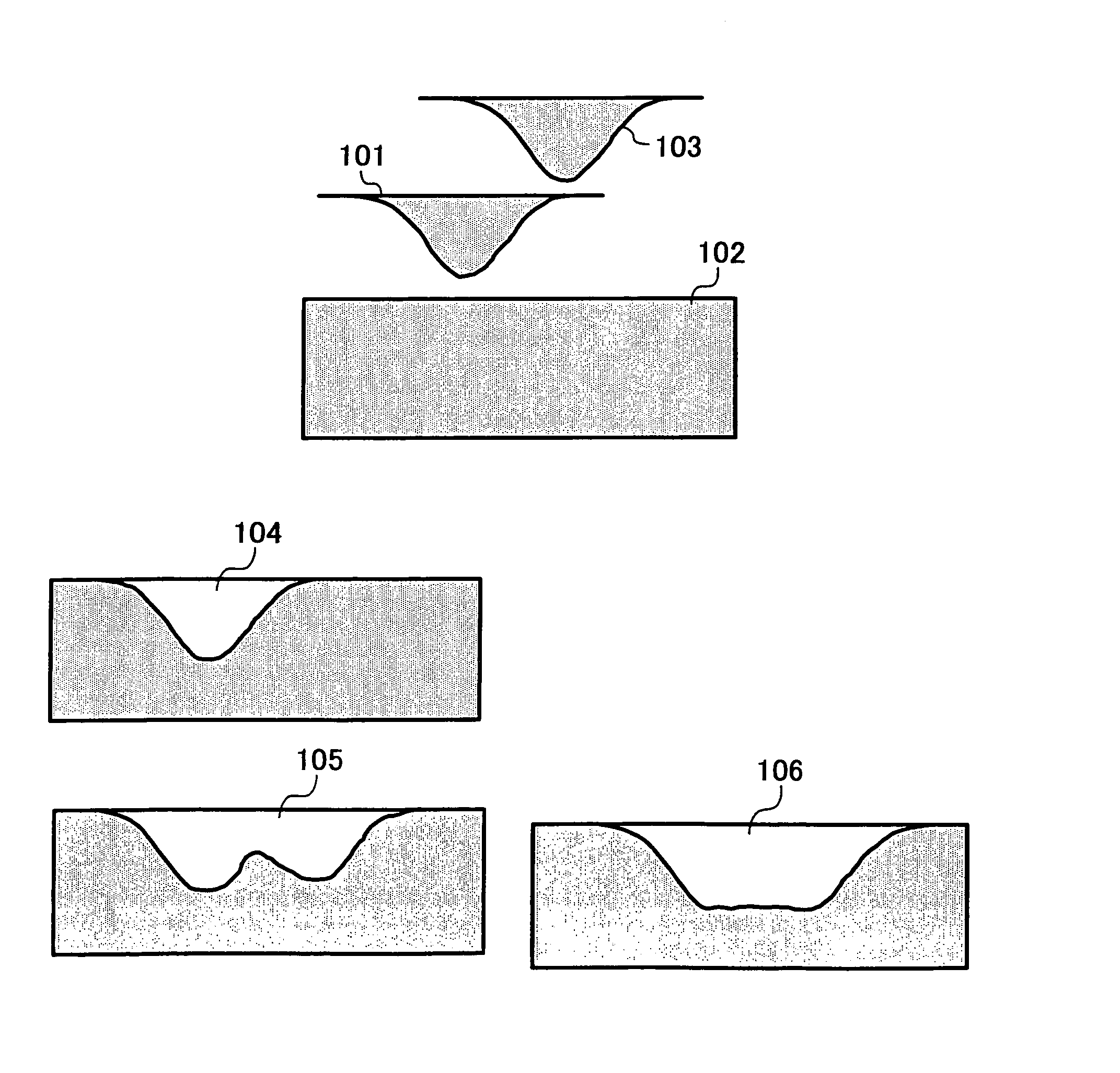
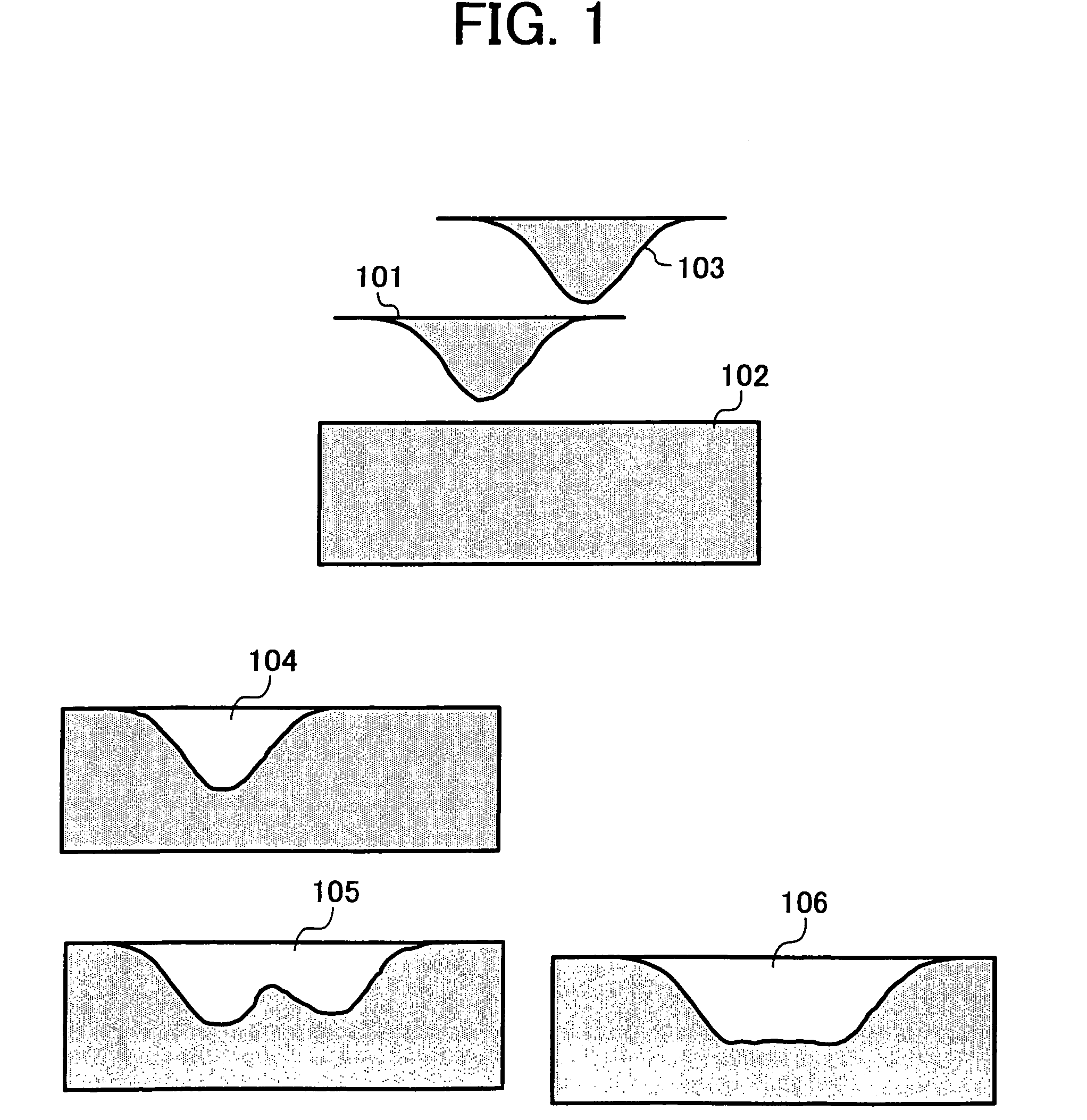
[0064]An example of the laser working method of the present invention will be explained with reference to FIG. 1.

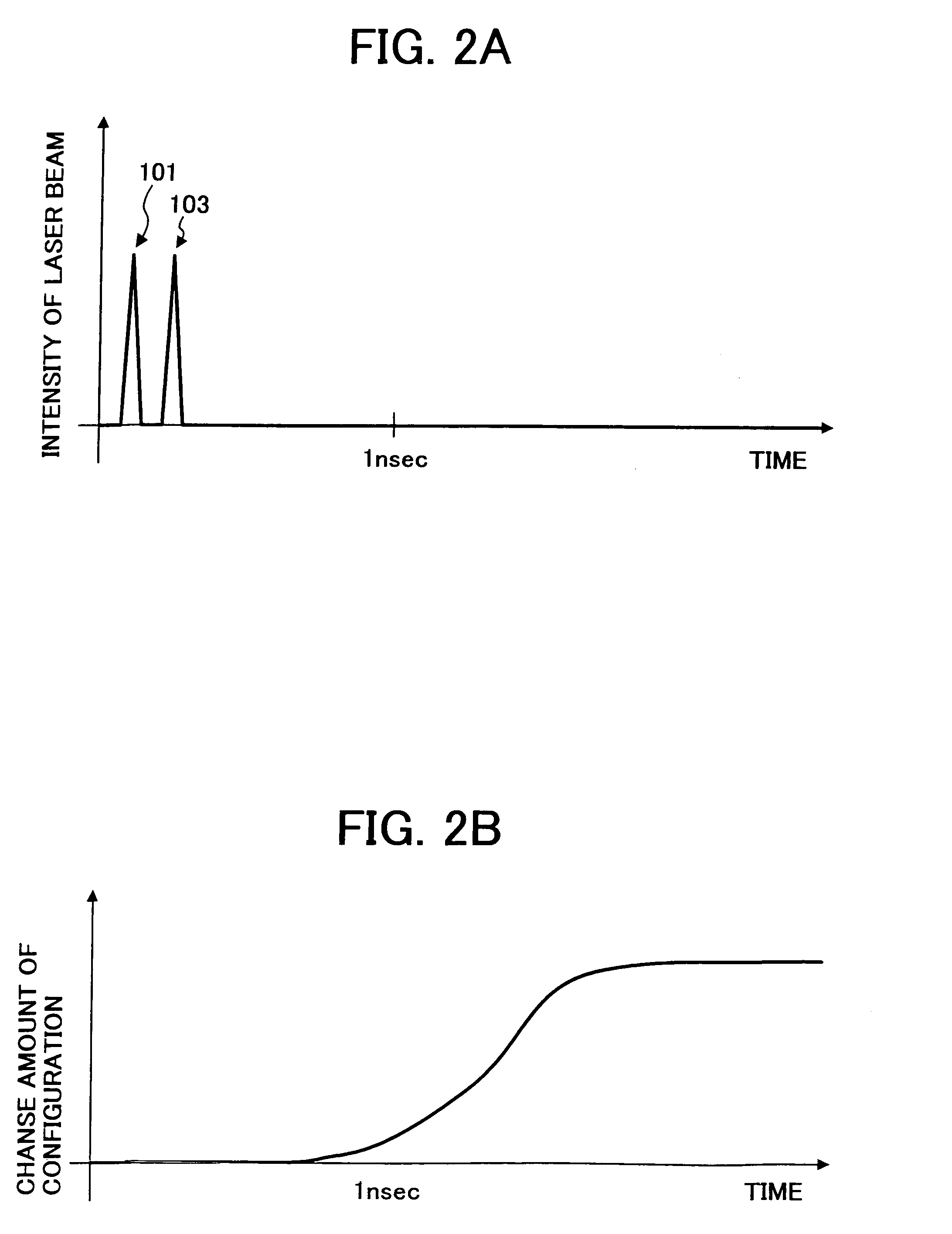
[0065]A first pulse laser beam 101 having a pulse time width of 100 fs is applied to an object 102 to be worked, and then a second pulse laser beam 103 having the same pulse time width of 100 fs is applied to the object. The worked shape with the first pulse laser beam is as indicated by 104. When the second pulse laser beam is applied after the termination of the working with the first pulse laser beam (that is, a few or several nanoseconds or more thereafter), the worked shape is as indicated by 105 in which a working efficiency decreases at an inclined surface formed with the first pulse laser beam. According to an example of the present invention, a worked shape is as indicated by 106 when the second pulse laser beam is applied 200 fs after the first pulse laser beam is applied. At that time, the intensity of the pulse laser beams applied to the working surface of the...

example 2

[0069]In Example 2, the intensity of at least one of the above plural pulse laser beams is adjusted with an ND filter or a polarization element. A device is preferably provided for adjusting the intensity of each of the laser beams so that their relative intensities may be freely varied. In the following, Example 2 will be explained with reference to FIG. 3.

[0070]First, a first pulse laser beam 301 having a pulse time width of 100 fs is applied to an object 302 to be worked. Then, a second pulse laser beam 304 of which intensity is adjusted to a half of that of the first pulse laser beam through the ND filter 303 is applied to the object 200 fs after the application of the first pulse laser beam. A worked shape having a three-dimensional step 305 can be obtained after the termination of working.

[0071]According to this Example, the three-dimensional worked shape can be realized by working, while the relative intensities of the plural pulse laser beams are varied.

example 3

[0072]In Example 3, a diffractive optical element is used for splitting a pulse laser beam. This will be explained with reference to FIG. 4.

[0073]A single pulse laser beam 401 is split into non-diffracted light beam 403 and plural primary diffracted light beams 404 by a diffractive optical element 402. At this time, the intensity ratio off the non-diffracted light beam 403 and plural primary diffracted light beams 404 is variable by appropriately designing the structure of the diffraction optical element 402. When a collimator lens 405 is installed downstream the beam splitting, the beams can be converted to plural parallel pulse beams. In this case, there is no time delay between the plural primary diffracted light beams 404, whereas there is a time delay between the non-diffracted light beam and plural primary diffracted light beams.

[0074]According to Example 3, the number and the intensity distribution of the split laser beams can be varied in various ways depending upon the desi...


PUM

PropertyMeasurementUnit
timeaaaaaaaaaa
timeaaaaaaaaaa
time widthaaaaaaaaaa

Abstract

A laser-working method is disclosed, which includes the steps of splitting a single pulse laser beam having a time width of not more than 500 picoseconds into plural pulse laser beams; subjecting said plural pulse laser beams to time delaying, and adjusting a working surface-irradiating shape, an intensity distribution and a working surface-irradiating position of each of the plural pulse laser beams; working a target object to be irradiated, while the respective working surface-irradiating shapes of said plural laser beams are partially or entirely spatially overlapped with each other or one another; and setting to a time interval of from a pulse width to 1 nanosecond a time period during which each of the pulse laser beams is irradiated.

Description

BACKGROUND OF THE INVENTION[0001](1) Field of the Invention[0002]The present invention relates to a method and an apparatus for directly working a material to be worked, with irradiating plural ultrashort-pulse laser beams. Particularly, the invention relates to a laser-working method and an apparatus for forming a two-dimensionally or three-dimensionally fine shape in a short time. The invention is directed to a method and apparatus for producing MEMS elements requiring high-precision parts needing fine shapes and master plates thereof as well as optical elements such as diffraction optical elements, holographic elements and photonic crystals and master plates thereof.[0003](2) Related Art Statement[0004]JP-A 10-113782 and JP-A 5-57464 describe methods for working target objects through continuously irradiating plural short-pulse laser beams. They are aimed at preventing damages of a vicinity around a working site through irradiation with intense laser beams having a short time wid...

Claims


Application Information

Patent Timeline
Patent Type & Authority Patents(United States)
IPC IPC(8): B23K26/00G02B6/00B23K26/04B23K26/067
CPCB23K26/0604B23K26/0608B23K26/067B23K26/0656B23K26/0635B23K26/0624B23K26/066
Inventor SEO, MANABUYAMADA, YASUFUMI
Owner RICOH KK
Why Eureka
Try Eureka