
Method and device for determining an open-circuit voltage profile of a vehicle battery, dependent on a state of charge

a technology of open-circuit voltage and vehicle battery, applied in the direction of battery/fuel cell control arrangement, instruments, transportation and packaging, etc., can solve the problems of vehicle battery chemical and electrical properties change, vehicle battery ageing, etc., and achieve the effect of more precise determination

Active Publication Date: 2019-01-29
ROBERT BOSCH GMBH
View PDF17 Cites 1 Cited by
  • Summary
  • Abstract
  • Description
  • Claims
  • Application Information

AI Technical Summary

Benefits of technology

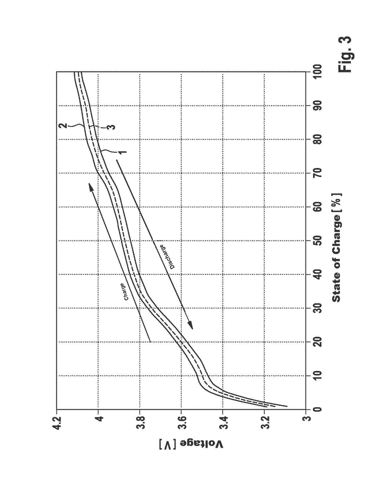
[0007]The method according to the invention and the battery management system according to the invention are advantageous because no additional hardware besides the otherwise required hardware in the user operation and also no skilled personnel are necessary in order to obtain a regular determination of the state-of-charge-dependent open-circuit voltage profile of a vehicle battery. A particularly precise determination of the state-of-charge dependent open-circuit voltage profile is achieved by the weighted interpolation, whereby the results of algorithms based thereupon also lead to improved calculation results. The influences of errors, such as, e.g., on account of uneven charging and discharging current can be compensated.
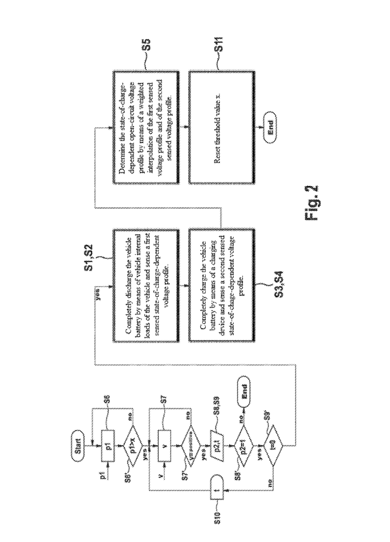
[0008]A first decision parameter is preferably queried in an introductory step of the method and a decision whether said method is to be continued occurs on the basis of a comparison of the first decision parameter to a given threshold value. The first decision parameter is particularly a parameter which describes the mileage on the vehicle, a charge throughput of the vehicle battery and / or an energy throughput of the vehicle battery. In this way, the method is carried out if it is likely that a state-of-charge-dependent open-circuit voltage profile determined at an earlier point in time no longer corresponds to the actual state-of-charge-dependent open-circuit voltage profile. Constant, time consuming measurements are therefore avoided.
[0010]It is advantageous if a query of a second decision parameter takes place prior to the step of the method involving the complete discharging of the vehicle battery, wherein an input of the second decision parameter is preferably facilitated by a user and wherein the method is ended or continued dependent upon the second decision parameter. It is thereby achieved that a user has the option of preventing the method from being carried out prior to discharging the vehicle battery. The situation can thus be prevented that the vehicle is in a non-operable state if usage is desired by the user.
[0011]In addition, it is advantageous if a query of a delay time occurs prior to the step in the method involving discharging the vehicle battery, wherein an input of the delay time is enabled preferably by a user and wherein the method is delayed in a step following the query of the delay time for the duration of the defined delay time, in the event said delay time is not equal to zero. In so doing, the discharging of the vehicle battery can be moved to a later point in time. The input of said delay time by the user is advantageous because the user can assess when the vehicle is not needed for use.
[0012]A query of an execution time period particularly takes place prior to the procedural step of completely discharging the vehicle battery, wherein an input of the execution time period is preferably enabled by a user and wherein a battery current which flows while discharging the vehicle battery and / or while charging said vehicle battery is selected in such a manner that the method is completed in the predefined execution time period. In the case of a short execution time period, the vehicle is again ready for use at an earlier point in time. In the case of a long execution time period, more precise values for the state-of-charge-dependent open-circuit voltage profile can be determined. The input of this execution time period by the user is advantageous because said user can assess when the vehicle is again required for use and therefore the input of a corresponding execution time period is possible.
[0013]In a preferred embodiment of the invention, a pre-charging of the vehicle battery, during which the vehicle battery is completely charged, takes place prior to the procedural step of completely discharging the vehicle battery. This has the effect that a first sensed, state-of-charge-dependent voltage profile can be determined across all charging states. The result of the determination is therefore more precise because no charging states occur for which a second sensed state-of-charge-dependent voltage profile is sensed.

Problems solved by technology

Vehicle batteries for automotive applications are subject to ageing which changes the chemical and electrical properties of the vehicle battery.

Method used


Image

  • Method and device for determining an open-circuit voltage profile of a vehicle battery, dependent on a state of charge
  • Method and device for determining an open-circuit voltage profile of a vehicle battery, dependent on a state of charge
  • Method and device for determining an open-circuit voltage profile of a vehicle battery, dependent on a state of charge

Examples


first embodiment

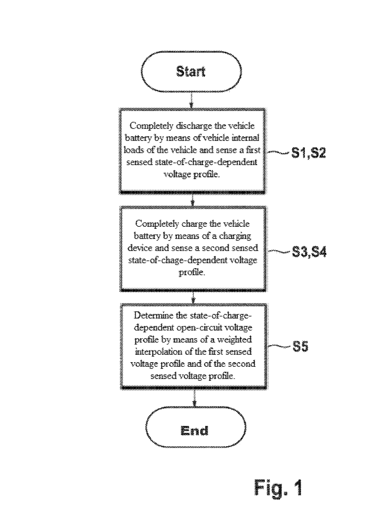
[0023]FIG. 1 shows a flow diagram of the method according to the invention in a The method can, for example, be started by means of a start signal of an independent vehicle system of by means of a request by a user.

[0024]In a first procedural step S1, a complete discharging of the vehicle battery occurs by means of vehicle-internal loads of the vehicle. Such components of the vehicle are designated as vehicle-internal loads, which are also available during a user operation of the vehicle. Examples of such components include, for example, a heater (if applicable compensated by the simultaneous operation of a cooling system), fans, pumps, electric machines or similar components. In this regard, those loads are to be preferred which are characterized by a constant current consumption.

[0025]When completely discharging the vehicle battery by vehicle-internal loads of the vehicle in the first procedural step S1, it is advantageous if the discharging is carried out with discharging curren...

second embodiment

[0036]In this second embodiment, a first decision parameter p1 is however queried in an introductory procedural step S6. The first decision parameter p1 can be provided by other systems located in the vehicle or by the battery management system itself. Examples for the first decision parameter p1 are a current datum, the mileage on the vehicle, a charge throughput of the vehicle battery or an energy throughput of the vehicle battery. The queried first decision parameter p1 is compared to a predefined threshold value x in procedural step S6′. This threshold value x can be predefined in the battery management system during the course of a manufacturer or user configuration. If the obtained decision parameter p1 is greater than the threshold value x, the method is then continued. If the obtained decision parameter p1 is smaller than the threshold value x, the method then branches back to the introductory procedural step S6, wherein said step S6 is again carried out.

[0037]In the second ...


PUM


Abstract

The present invention relates to a method and to a battery management system which are suitable for determining an open-circuit voltage profile (3) of a vehicle battery, dependent on a state of charge, in a vehicle. In this context, the following occur: complete discharging (S1) of the vehicle battery by vehicle-internal loads of the vehicle, sensing (S2) of a first sensed, state-of-charge-dependent voltage profile (1) during the discharging (S1) of the vehicle battery, complete charging (S3) of the vehicle battery by a charging device, sensing (S4) of a second sensed state-of-charge-dependent voltage profile (2) during the charging (S3) of the vehicle battery, and determination (S5) of the state-of-charge-dependent open-circuit voltage profile (3) by means of a weighted interpolation of the first sensed voltage profile (1) and of the second sensed voltage profile (2).

Description

BACKGROUND OF THE INVENTION[0001]The present invention relates to a method and a device, particularly a battery management system, for determining an open-circuit voltage profile of a vehicle battery, dependent on a state of charge, in a vehicle.[0002]Vehicle batteries for automotive applications are subject to ageing which changes the chemical and electrical properties of the vehicle battery. In this context, capacity and energy content are reduced whereas the inner resistance generally increases.[0003]Particularly the open-circuit voltage of the vehicle battery is subject to ageing and changes the voltage profile thereof dependent on a state of charge in some vehicle batteries. This affects different algorithms which are carried out by means of a responsible battery management system. Said algorithms include, for example, determining the charging state and determining the capacity. In addition, the accuracy of said algorithms carried out by the responsible battery management syste...

Claims


Application Information

Patent Timeline
Patent Type & Authority Patents(United States)
IPC IPC(8): G01R31/36
CPCB60L11/1861G01R31/3835G01R31/367B60L58/12Y02T10/70
Inventor RUEGER, MICHAELBOEHM, ANDRE
Owner ROBERT BOSCH GMBH
Learn More