
Relativistic magnetron using a virtual cathode

a technology of relativistic magnetrons and virtual cathodes, applied in the direction of magnetrons, electric discharge tubes, electrical apparatus, etc., can solve the problem of limited life of high-power relativistic magnetrons

Active Publication Date: 2019-01-29
STC UNM
View PDF15 Cites 0 Cited by
  • Summary
  • Abstract
  • Description
  • Claims
  • Application Information

AI Technical Summary

Benefits of technology

The present invention provides a magnetron that has a virtual cathode instead of a physical cathode, which allows for a more stable and durable cathode. Additionally, the invention provides a magnetron with a cathode that is located outside the interaction space of the magnetron, which reduces the likelihood of deterioration. The invention also includes the use of a vacuum channel that changes in radius to create a region where the current of the electron beam exceeds the space-charge-limiting current, which results in a virtual cathode. Finally, the invention provides a magnetron that has a channel that receives an electron beam that is in communication with a larger radius channel, which serves as an interaction space where a virtual cathode is formed that may be used to power the magnetron.

Problems solved by technology

The lifetime of high power relativistic magnetrons is limited by the intense electron bombardment of the cathodes that leads to their destruction.

Method used


Image

  • Relativistic magnetron using a virtual cathode
  • Relativistic magnetron using a virtual cathode
  • Relativistic magnetron using a virtual cathode

Examples


Embodiment Construction

[0026]Detailed embodiments of the present invention are disclosed herein; however, it is to be understood that the disclosed embodiments are merely exemplary of the invention, which may be embodied in various forms. Therefore, specific structural and functional details disclosed herein are not to be interpreted as limiting, but merely as a representative basis for teaching one skilled in the art to variously employ the present invention in virtually any appropriately detailed method, structure or system. Further, the terms and phrases used herein are not intended to be limiting, but rather to provide an understandable description of the invention.

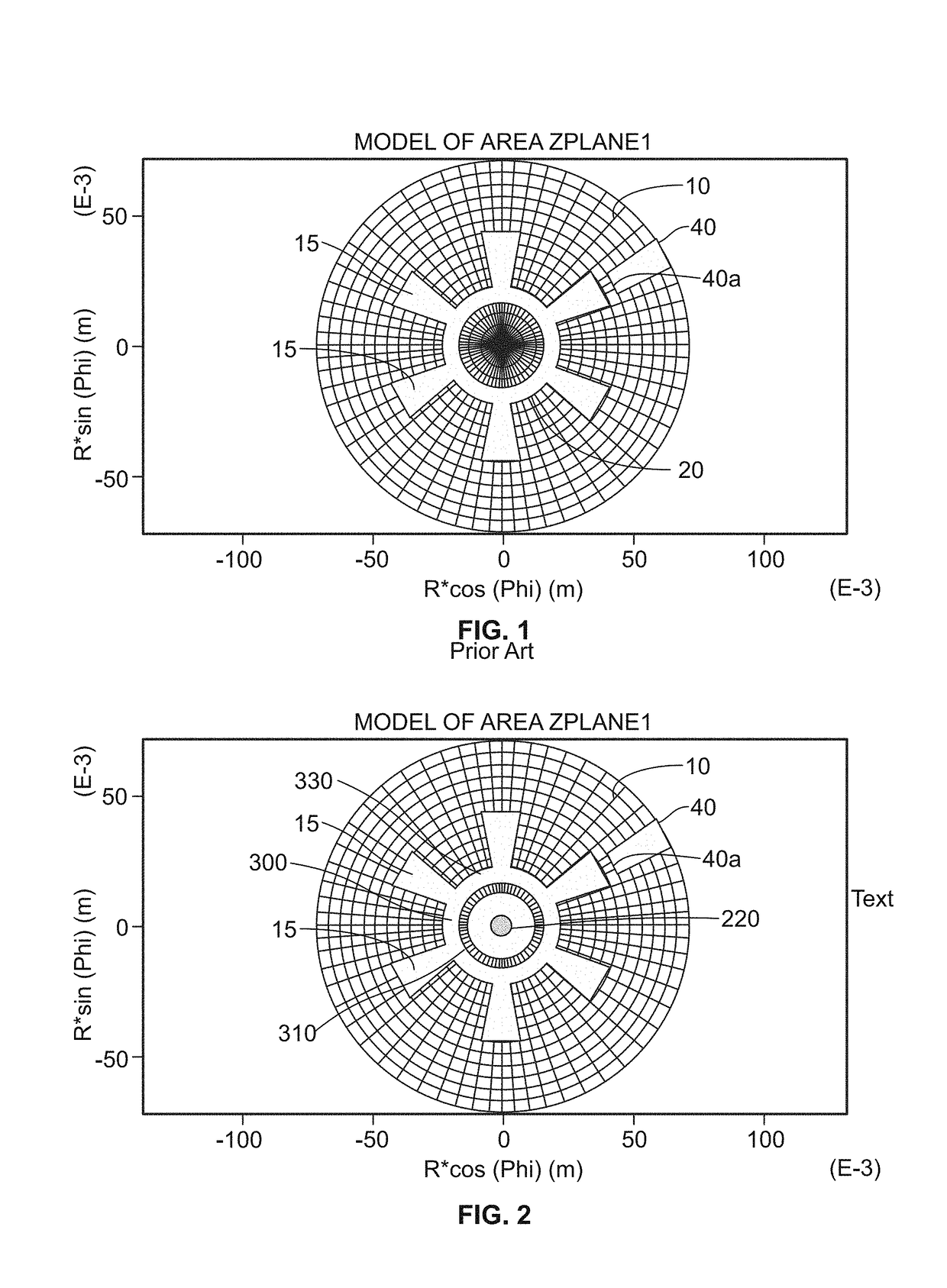
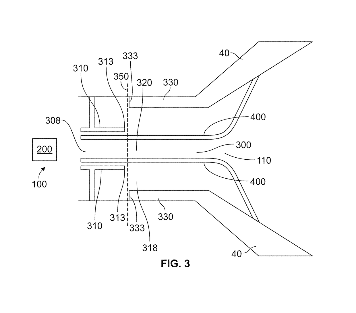
[0027]As shown in FIGS. 2 and 3, in one embodiment, the present invention provides a magnetron having an anode 10, a virtual cathode 220, which is created from an electron beam from source 200, which may be an electron gun or beam generator, and resonator cavities 15. A vacuum channel 300 is in communication with source 200. As shown, sourc...


PUM


Abstract

The present invention provides a relativistic magnetron including an anode with an entrant channel, the channel having an input end, an output end and a dimensional discontinuity between the ends. The channel is connected to the magnetron and has an anode defining an interaction space located between the dimensional discontinuity and output end. Also provided is a cathode, located upstream, a spaced distance away from the interaction space towards the input end, the cathode is adapted to send an electron beam into the interaction space where the electron beam forms a virtual cathode in the interaction space.

Description

RELATED APPLICATIONS[0001]This application is a Continuation-In-Part of U.S. Ser. No. 14 / 742,634, currently pending, which claims the benefit of U.S. Provisional Application No. 62 / 013,425 filed Jun. 17, 2014, both of which are herein incorporated by reference.STATEMENT REGARDING FEDERALLY SPONSORED RESEARCH & DEVELOPMENT[0002]This invention was made with government support under N00014-13-1-0565 awarded by the Office of Naval Research and under FA9550-15-1-0094 awarded by the Air Force Office of Scientific Research. The government has certain rights in the invention.INCORPORATION BY REFERENCE OF MATERIAL SUBMITTED ON A COMPACT DISC[0003]Not applicable.BACKGROUND OF THE INVENTION[0004]Magnetrons are widely used as powerful and compact sources for the generation of high power microwaves in a variety of applications. Such applications may include, but are not limited to, industrial microwave ovens, telecommunications equipment, lighting applications, radar applications, and military a...

Claims


Application Information

Patent Timeline
Patent Type & Authority Patents(United States)
IPC IPC(8): H01J25/50H01J23/02H01J23/20
CPCH01J25/50H01J23/20H01J23/02
Inventor SCHAMILOGLU, EDLFUKS, MIKHAIL I.
Owner STC UNM
Learn More